Meta description: P0412, P0418, P2440–P2447? The SAIS failure that hits every aging Toyota truck. Diagnosis, OEM repair vs. bypass kits, emissions legality, and real owner costs.
Reading time: ~12 minutes · Difficulty: diagnosis easy, OEM repair hard (manifold removal on V8s), bypass kit easy · Applies to: Toyota/Lexus trucks and SUVs with the secondary air injection system, roughly 2005–2018
If you own an aging Toyota truck, this failure isn’t a question of if. It’s when. The secondary air injection system (SAIS) fails on nearly every Toyota V6 and V8 truck from the mid-2000s onward, usually announcing itself with a check-engine light, a TRAC OFF light, and in many cases a sudden loss of power that owners describe as borderline dangerous in traffic. [community]
The dealer fix runs $2,000–$3,000. [vendor] The fix most owners actually choose costs under $500. This guide explains what the system does, why it dies, how to diagnose it properly, and which repair path makes sense for your truck and your situation.
Parts and tools
For diagnosis (either path):
OBD-II Bluetooth scanner. Pulling codes is step zero. [community]
Toyota-compatible scan cable with Techstream. For the air-injection active test. [community] Shadetree: a Mini VCI cable (about $25) plus the Techstream software gets you the same active test as the dealer tool.
Spare fuses and a pump relay. The cheap-first electrical checks. [manual: GX470]
For the bypass route:
Bypass kit: Hewitt Technologies Gen 2 ($450–$495) [vendor], or a Gen 1-style kit ($48–$78) [community]
Stainless block-off plates, about $33 shipped. [community] Required if any valve is stuck open. Smart preventive maintenance otherwise.
Basic hand tools. V6 installs are 30-minute plug-and-play. V8 kits need a wire run through the firewall to the ECM. [community]
For the OEM repair route:
Air pump assembly, switching valves, and possibly the air injection driver module. Order by VIN for your exact year and model. [vendor]
Intake manifold gaskets. The whole system lives under the manifold on the 4.7L V8s. [vendor]
What the SAIS does (and why yours is dying)
The secondary air injection system is a cold-start emissions device. For a short period after a cold start (owners consistently report roughly 30–60 seconds [community]), an electric air pump pushes fresh air through switching valves into the exhaust manifolds. The extra oxygen helps the catalytic converters light off faster, cutting cold-start emissions. Once the cats are hot, the pump shuts off and the system goes dormant until the next cold start.
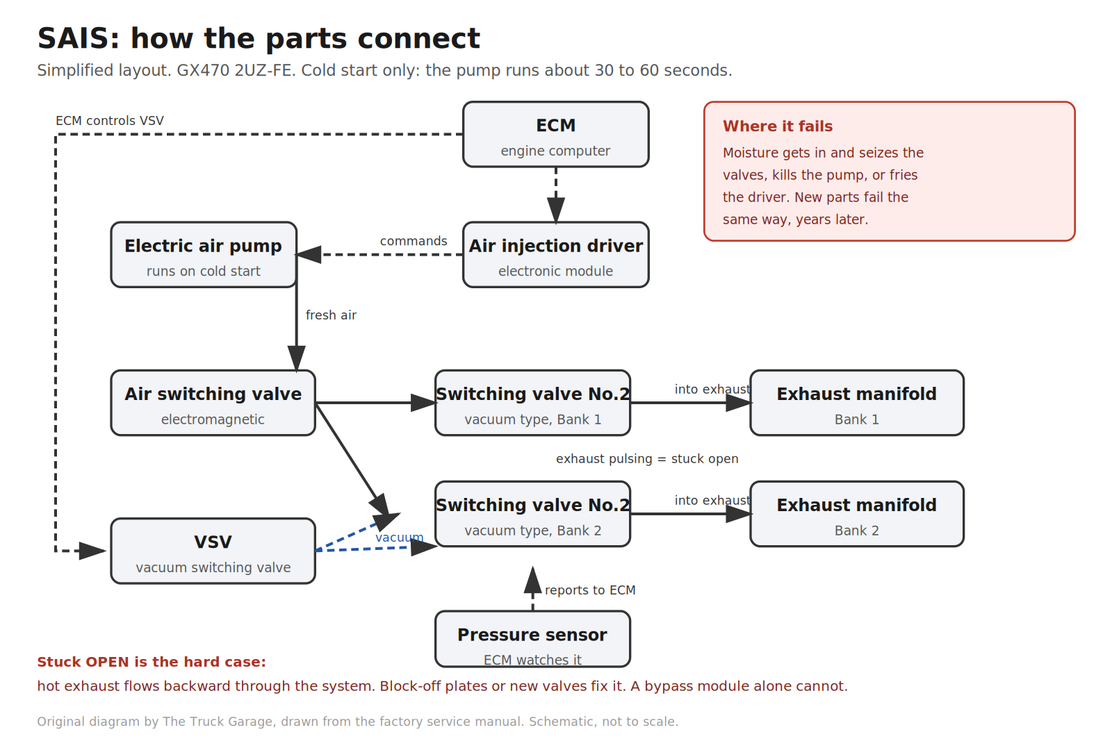
The system has four main components: the air pump (an electric blower), the switching valves (which open and close the air path to each bank), the air injection driver module (which the ECM uses to switch the pump and valves), and the pressure sensors the ECM uses to monitor everything. [manual: GX470]
Original diagram by The Truck Garage. SAIS component layout on a V8 truck, drawn from the factory service manual. Schematic, not to scale.
The failure mode is depressingly consistent: moisture gets in. Toyota’s own technical service bulletin T-SB-0160-11 documents water intrusion into the air injection pump assemblies causing exactly these fault codes. [TSB] Corrosion seizes the switching valves (open or closed), kills the pump, or takes out the driver electronics. Heat cycles and age do the rest. Replacing the parts doesn’t fix the design. The new parts fail the same way, years later.
Symptoms
The classic presentation: check-engine light plus TRAC OFF light, sometimes with the truck dropping into limp mode. Severely reduced power until you restart. The truck often drives fine between episodes, which is why owners sometimes clear the codes and hope, then get stranded again on the next cold morning. [community]
Clearing the codes buys you a normal drive until the next cold start. Then the ECM runs its SAIS self-test and the codes return. [community]
The codes
SAIS codes cluster in three families:
P0412. Air switching valve circuit fault. [manual: GX470]
P0418 / P0419. Air pump relay circuit faults. [manual: GX470]
P2444. Pump stuck ON, Bank 1. P2445. Pump stuck OFF, Bank 1. [manual: GX470]
P2446 / P2447. Same pair, Bank 2. [manual: GX470]
P2440. Switching valve stuck open, Bank 1. P2441. Stuck closed, Bank 1. [manual: GX470]
P2442 / P2443. Same pair, Bank 2. [manual: GX470]
P1441 / P1444. Valve stuck open on some applications. [community]
This distinction matters enormously: a dead pump with healthy closed valves is the easy case. Valves seized open are the hard case, because exhaust is leaking backward through the system. And no bypass kit can seal a valve that’s physically stuck open. More on that below.
Diagnosing it properly
Don’t throw parts at this. The diagnostic tree is short and logical.
Check fuses and the pump relay first. Electrical codes (P0412/P0418/P0419) can be as dumb as a blown fuse or a corroded relay. The manual’s trouble areas for these codes start with opens and shorts in the valve and pump drive circuits before condemning parts. [manual: GX470]
The cold-start listen test. On a stone-cold engine, have someone start the truck while you stand at the open hood. You should hear the air pump whir for roughly half a minute after startup. [community] Silence with pump codes means a dead pump (or no power to it). A pump that runs but you still get valve codes means the valves aren’t doing their job.
A scan tool with an active test is the definitive check. Toyota’s TSB procedure uses Techstream’s air-injection active test to command the pump on and watch for voltage at the pump and a pressure rise. [TSB] If voltage arrives and the pump doesn’t run, the pump is dead. If the pump runs and pressure doesn’t behave, suspect valves or plumbing.
Determine whether valves are stuck open or closed. This is the fork in the road for your repair decision. Stuck-closed valves (P2441/P2443) just don’t flow air. Annoying to the ECM, harmless to the engine. Stuck-open valves (P2440/P2442, P1441/P1444) let hot exhaust pulse backward into the system, which is what destroys pressure sensors and pumps downstream. The ECM detects this via its pressure sensor. It literally watches for exhaust pulsation when the system should be sealed. [manual: GX470]
Option 1: The OEM repair (expensive, correct, compliant)
The factory repair means replacing the failed components: pump assembly, switching valves, sometimes the driver module. On the 4.7L V8s the entire system lives under the intake manifold, so the job includes manifold removal. That’s a big chunk of the labor. [vendor]
Expect $2,000–$3,000 at a dealer for parts and labor. [vendor] One GX470 owner was quoted $4,000 by Lexus for the pump-and-valve job. [community]
Option 2: The bypass kit (cheap, effective, popular)
This is what the forums overwhelmingly recommend, and it’s worth understanding what the kits actually do rather than treating them as magic boxes.
Gen 1 kits (including budget options from vendors like Slyfox and FireWaterMarine, roughly $48–$78 [community]) intercept the system so the pump never runs and the ECM never sees a fault for mechanical failures. Dead pumps, seized valves. They typically wire into the starter circuit so the emulation is active from crank. [community]
Gen 2 kits (Hewitt Technologies, $450–$495 [vendor]) go further. They fully emulate the SAIS electrically, which means they can also cover electrical fault codes that Gen 1 kits can’t. They stay compatible with later ECM software flashes, and the emissions monitors show as ready/complete. They ship with stainless block-off plates. [vendor]
Block-off plates deserve their own callout. The plates bolt between the switching valves and the exhaust manifolds, physically sealing off the leak path. They’re cheap (one owner paid about $33 shipped [community]) and many owners install them preventatively at the same time as a bypass. If your valves are verified closed and healthy, you can often skip the plates. But on a rusty truck, the plate bolts themselves can be the hardest part of the job, so plenty of owners do it once, while they’re in there. [community]
Install difficulty is genuinely DIY-friendly: owners routinely report 30-minute plug-and-play installs on the V6 trucks. [community] The V8 “3-valve” kits need some wiring run through the firewall to the ECM. Still a driveway job if you’re comfortable tapping a harness. [vendor]
The emissions question
The secondary air injection system is an emissions device, and federal law (the Clean Air Act’s tampering prohibition) prohibits defeating or bypassing emissions controls on road vehicles. The kit vendors sell these explicitly “for off-road use only.” [vendor]
If your state or county does emissions inspections, a visual inspection can fail you regardless of what the monitors say. And a sharp inspector knows what block-off plates look like.
Many owners in non-inspection areas run bypass kits for years without issue, and that’s the reality of the community. But go in with your eyes open: the OEM repair is the only option that keeps the truck unambiguously compliant everywhere.
Which option should you choose?
Pump dead, valves verified closed, no inspection worries. Bypass kit. This is the overwhelming community consensus and the best dollars-to-outcome ratio in this entire guide.
Any valve stuck OPEN. You need block-off plates at minimum (to seal the exhaust leak path), or the OEM valve replacement. A bypass module alone cannot fix a physically open valve.
Electrical codes (P0412/P0418). Check fuses/relay/wiring first. If the driver or ECM side is genuinely dead, lean toward a Gen 2-style full-emulation kit rather than Gen 1.
You face emissions inspections, or you just want it factory. OEM repair. Expensive, correct, compliant.
Nothing failed yet and you’re doing preventive maintenance. Some owners install the bypass before failure, often skipping the block-off plates while the valves are still healthy and the bolts aren’t rusted solid. [community]
Can you just ignore it?
The system only operates for under a minute on cold starts. It has no effect on power, fuel economy, or drivability once warm. [community] The truck runs fine with a dead SAIS. The problems are the check-engine light (you’ll never know when a new, unrelated code appears), the limp-mode episodes some trucks throw, and inspections. Ignoring it indefinitely is common. Ignoring it knowingly is fine. Ignoring it unknowingly is how a $200 problem becomes a $2,000 one.
FAQ
Will a failed SAIS damage my engine?
No. It only runs briefly on cold starts and has no role in normal operation. The risk is to your wallet and your inspection sticker, not your engine. [community]
Can I just clear the code and keep driving?
You can, and the truck will drive normally until the next cold start. Then the ECM re-runs its self-test and the light returns, along with any limp-mode behavior your truck exhibits. [community]
Does the bypass affect gas mileage or power?
No. The system is inactive 99% of the time anyway. Emulating it changes nothing about how the truck runs warm. [community]
Will I pass emissions with a bypass kit?
Maybe, maybe not. Gen 2 kits report monitors as ready [vendor], which satisfies OBD-based inspections in many areas. But a visual inspection can still catch block-off plates, and defeating emissions equipment violates federal tampering law regardless. Know your local inspection type before deciding.
My 2003–2004 GX470 doesn’t have this system?
Correct, as far as the community has documented. The SAIS arrived with the VVT-i 2UZ-FE update. If you have a pre-2005 truck, don’t chase SAIS codes. Look elsewhere. [community]
Why didn’t Toyota just recall it?
They extended the warranty to 10 years/150k miles on the Tundra, but never on the GX470, 4Runner, LX470, or Land Cruiser. A sore point with owners to this day. That extension is long expired by now. [community]
Bottom line
The SAIS failure is a design flaw, not a maintenance failure, and the owner community solved it better than Toyota did. Diagnose properly, pick your path based on your valves and your inspection reality, and fix it once.
Meta description: The 2UZ-FE timing belt and water pump service every 90k miles. Procedure overview, torque specs, parts list, and owner tips for the GX470, 4Runner V8, Land Cruiser 100, Tundra, and Sequoia.
Every “just bought a 200k-mile GX470” thread ends at the same place: when was the timing belt last done? On the 2UZ-FE, that belt is the difference between a 400,000-mile engine and a very heavy paperweight. This guide covers when to do it, what to replace while you’re in there, the procedure in overview, and the torque specs that matter. All checked against the factory service manual for the GX470 and cross-checked with owners who’ve done it in their driveways.
The 2UZ-FE is a timing-belt engine with no warning lights and no second chances. The factory manual instructs setting the crankshaft to a specific pre-removal position (about 50° before top dead center) and warns that turning things at the wrong angle can slam valves into pistons. On the VVT-i engines (2005 and up), that contact bends valves. [manual] The owner community is even more specific. The pre-VVT-i engines (1998–2004) are widely regarded as non-interference. The VVT-i engines (2005 and up) are interference. A broken belt there means bent valves and, often, a dead engine. [community] Owners have also reported belt fibers starting to tear at just 30% over the mileage limit. [community]
The hard lesson from the forums: age kills belts as much as mileage does. A 135k-mile original belt on a 20-year-old truck looked far worse than its odometer suggested. The engine ran noticeably better once a fresh Aisin kit went on. Cam timing had been wandering as the old belt stretched. [community]
When to do it
The book and the community agree: every 90,000 miles or 108 months. That is the Lexus published interval for the timing belt. [manual] Several owners add a time rule of roughly 6–7 years regardless of mileage, because a truck that’s only been driven 8k a year still has a belt degrading on the same schedule. [community] If you just bought a used 4.7 and there’s no receipt or service history showing the belt was done, assume it wasn’t. Check the Lexus Drivers service history tool for dealer-reported services before trusting a seller’s word. [community]
Which vehicles this covers
This guide is procedure-verified for the Lexus GX470, 2003–2009 (the factory manual this was built from). The same 2UZ-FE 4.7L V8 also lives in the Toyota 4Runner V8 (4th gen, 2003–2009), Toyota Land Cruiser 100 and Lexus LX470 (1998–2007), Toyota Tundra 4.7 (2000–2009), Toyota Sequoia 4.7 (2001–2009), and the V8 Prado 120 in markets that got it. The procedure is extremely similar across these. But torque specs and small parts differ by year, so confirm against your own model-year manual before wrenching. It does not apply to the GX460 or GX550. Those use different engines with timing chains and have no scheduled belt service.
Parts and tools
Everything for the job in one place, before you turn a single bolt.
Parts:
Aisin TKT-021 timing belt + water pump kit. Belt, water pump, hydraulic tensioner, idler pulleys, gaskets. [vendor] Aisin catalogs the TKT-021 for the full 2UZ-FE range, including every GX470 from 2003 to 2009. Buy from a reputable seller. Counterfeit Aisin kits exist. [community]
Camshaft seals (x2) and crankshaft front seal [community]
Timing cover gaskets [community]
Accessory (serpentine) belt, tensioner, and idler [community]
Fan pulley bracket bearing. Aisin FBT-002, OE-style. [community]
Radiator. Preventive. The plastic side tanks leak right around this age. [community]
Toyota Red Long Life coolant [community]
Tools:
Torque wrench that reaches 181 ft·lbf (245 N·m). That is the crank bolt spec. [manual]
Crankshaft pulley holding tool (SST 09213-70011 or equivalent) and damper puller [manual]. Shadetree options for the holder are below.
Lisle 24680 spill-free funnel, or any funnel plus patience. The Lisle seals to the radiator neck with twist-lock adapters and holds a column of coolant above the system so trapped air burps out without spilling. Nice to have, not required. [community]
1.27 mm hex wrench. Pins the tensioner in the compressed position during install. [manual] Note: 1.27 mm is exactly 0.05 inch, so a 0.05 in hex wrench is the same tool.
Standard socket set, jack and jack stands
What to replace while you’re in there
The labor to reach the timing belt is nearly identical to the labor for everything around it. Doing the belt alone and leaving a 90k-mile water pump behind is the classic false economy. The standard owner recommendation is the Aisin TKT-021 kit. Aisin is the OEM supplier. The kit bundles the water pump, timing belt, hydraulic tensioner, idler pulleys, and gaskets. [vendor] Owners report the kit (plus seals) covering everything needed for the job. [community]
Camshaft seals (x2) and crankshaft front seal. They’re behind the same covers and cost a few dollars each [community]
Timing cover gaskets. Brittle after 15+ years
Accessory (serpentine) belt and its tensioner/idler. All comes off during the job anyway
Fan pulley bracket bearing. Spins constantly, commonly noisy by belt-change time. The Aisin FBT-002 is the OE-style replacement. [community]
Thermostat, upper/lower radiator hoses, heater T-fittings. The plastic heater Ts under the intake are a known failure point on aging 2UZs, and the whole cooling system is drained for this job [community]
Radiator. The plastic side tanks start leaking right around this age. Several owners preemptively replace it during the belt service. [community]
One correction worth noting from the owner threads: it’s the starter that sits buried in the V of the engine (some owners do it at 240k as preventive maintenance), not the alternator. That one was a mix-up in the original thread. [community] Do not tear into the intake hunting for the alternator.
Fitment note: the TKT-021 is the correct kit for every 2UZ-FE, 1998 through 2009. [vendor] Don’t buy the TKT-001 by mistake. It looks similar but ships without the hydraulic tensioner.
The procedure (overview)
The factory procedure is a long chain of “remove X to reach Y.” Drain the coolant. Disconnect the battery. Pull the V-bank cover and engine covers. Remove the fan and fluid coupling with the shroud, the accessory drive belt, the power steering vane pump (hung aside without disconnecting hoses), the generator, and the A/C compressor (also hung aside, hoses attached). Then the idler pulleys, oil cooler pipe, timing covers, accessory belt tensioner, and fan bracket. Finally the crankshaft damper comes off and the belt is exposed. [manual]
Original diagram by The Truck Garage. Belt install order and timing mark positions, drawn from the factory service manual. Schematic, not to scale.
The steps that owners say demand the most care:
Set the crank before you touch the belt. With the covers off, the factory manual has you rotate the crankshaft to align its timing marks, verify the camshaft timing pulleys align with their timing marks, then back the crank off about 50° before top dead center, before releasing the tensioner. [manual] This is the interference-engine safety step. Skip it and the pistons and valves can meet when the belt comes off.
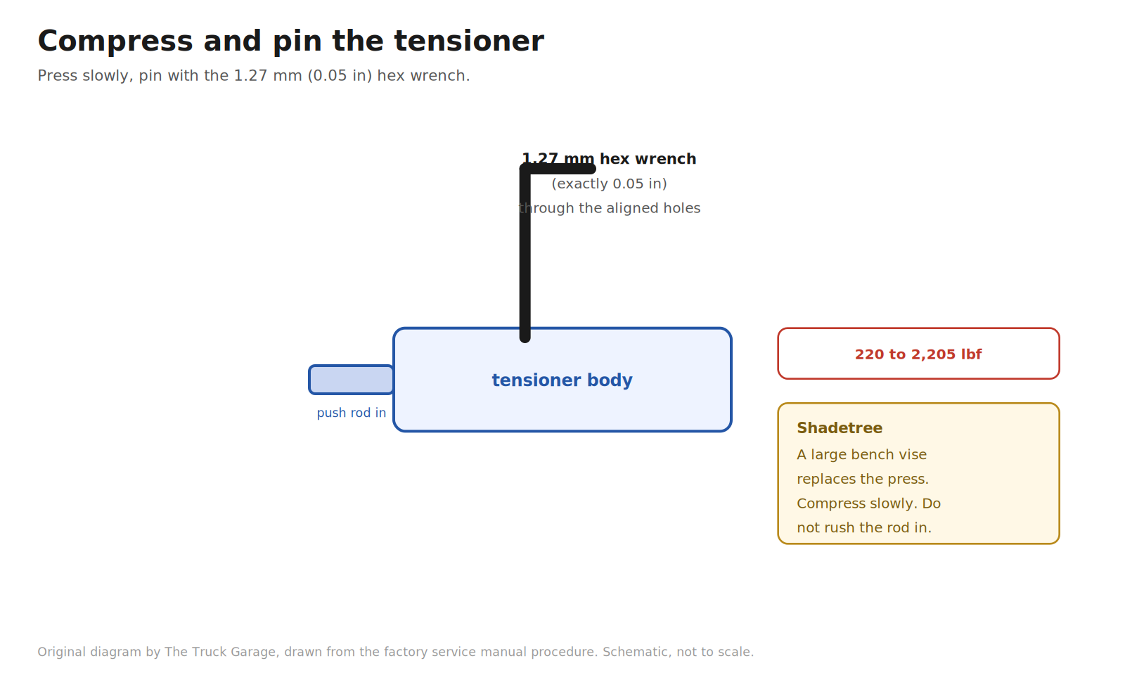
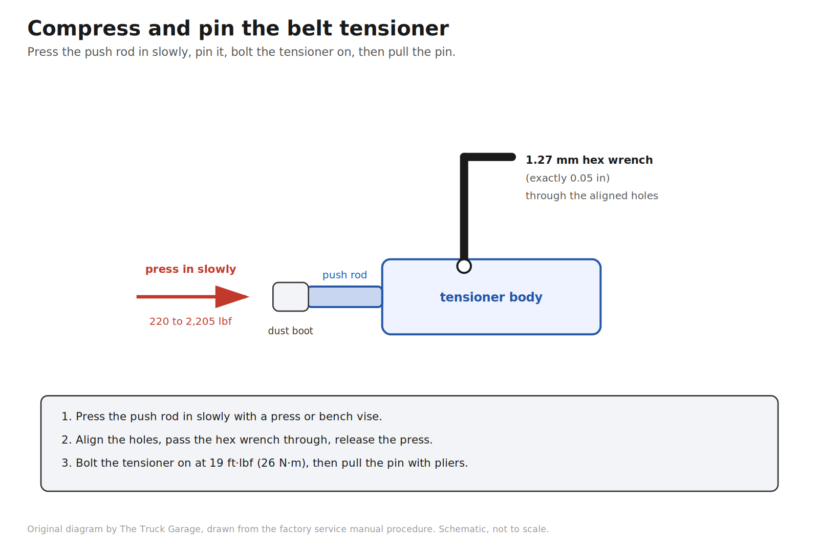
Compress and pin the tensioner. The hydraulic tensioner push rod is slowly compressed in a press (between about 220 and 2,200 lbf of pressure) and pinned in the compressed position with a 1.27 mm (0.05 in) hex wrench before it’s bolted on. [manual] No press in your garage. A large bench vise does the same job. Compress slowly. Owners buy a new tensioner with the kit rather than reusing the old one. A hydraulic tensioner that has been holding belt tension for 90k miles isn’t worth gambling on. [community]
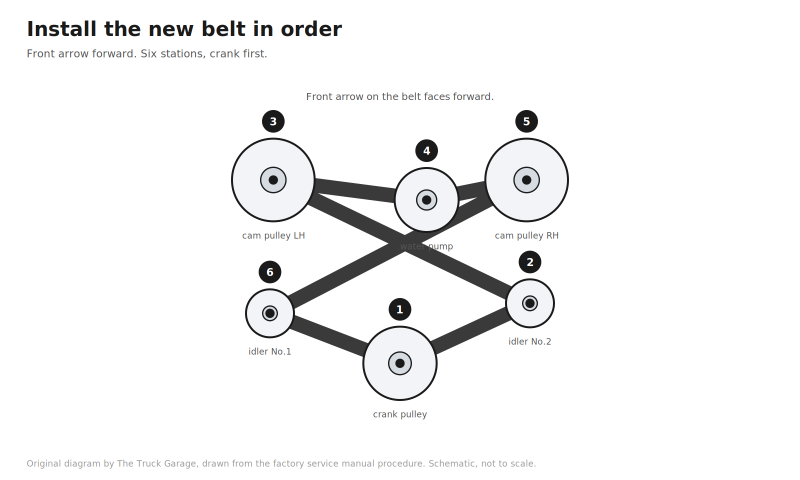
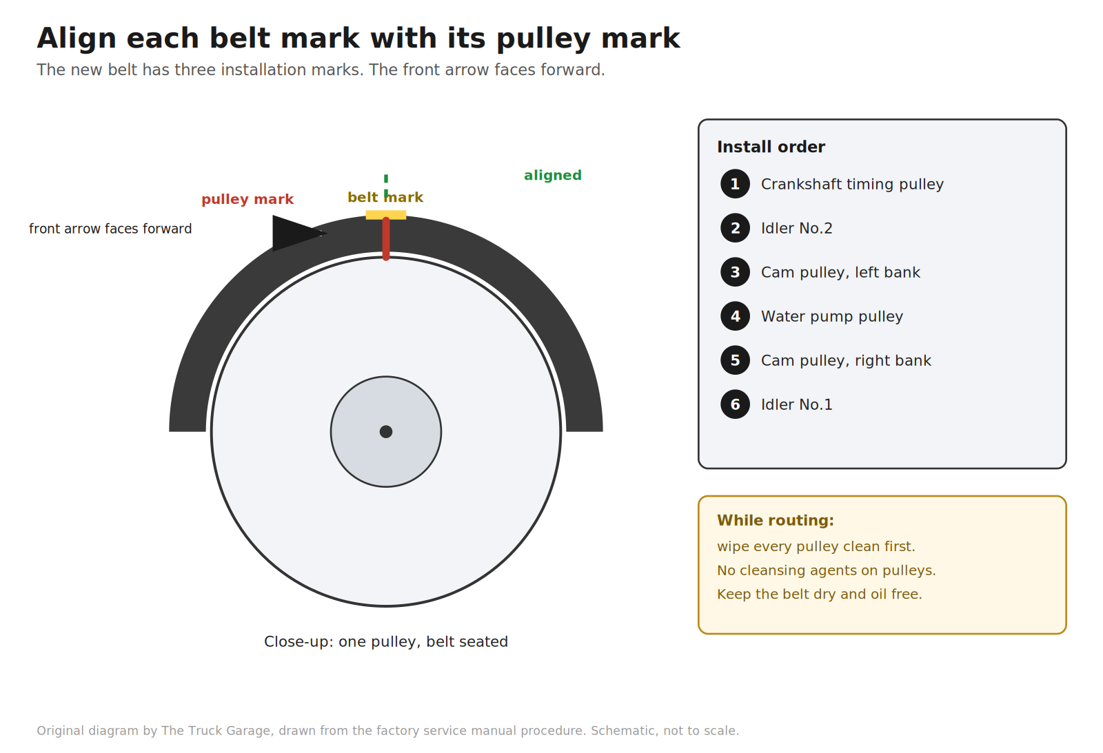
Install the new belt in order, marks aligned. The belt goes on in sequence. Crankshaft timing pulley, idler No.2, left-bank cam pulley, water pump pulley, right-bank cam pulley, idler No.1. The belt’s installation marks align to each pulley’s timing mark, with the belt’s front arrow facing forward. [manual] Pulleys get wiped clean. The manual specifically says no cleansing agents on them. [manual]
Verify before closing up. After tensioning, the crankshaft is turned clockwise two full revolutions and every pulley’s timing marks are rechecked. [manual] Miss this and a tooth-off mistake only shows up as a rough-running engine after everything’s bolted back together.
Refill and bleed the coolant carefully. The whole system was drained. A spill-free funnel on the radiator neck makes it easier to work air out of the V8’s long cooling circuit. An air pocket left in the system can cause a scary overheat on the test drive. [community]
Realistic time: a full weekend for a first-timer with a manual and patience. Specialty tools needed include a crankshaft pulley holding tool and a puller for the damper, plus a torque wrench that reaches the crank bolt spec. [manual]
No crank holder? Shadetree options
The crank bolt is the gatekeeper of this job. 181 ft·lbf (245 N·m), and you need the crank held still to break it loose and to torque it back down. If you don’t own the factory holding tool, here are the options owners actually use, ranked by sanity.
Electric impact for removal. A modern 1/2 in brushless impact with 1,000+ ft·lbf of breakaway torque zips the bolt off with the crank held by nothing but inertia. This is the current driveway standard. Never use the impact to install the bolt. Torque it to spec with a wrench. [community]
Fabricated holder. A length of flat steel bar with two holes drilled to match the pulley bolt holes, braced against the ground or the frame. Cheap, controlled, and safe if built stout. [community]
Torque converter window trick. Pull the transmission inspection cover, put a deep socket on a torque converter bolt, and rotate until it seats against the bell housing. Costs nothing. Make sure the socket is straight and fully seated so it can’t walk off at an angle. [community]
Loaner puller set. AutoZone, O’Reilly, and Advance loan harmonic balancer puller sets free with a refundable deposit. Note what those are: pullers, for getting the damper off after the bolt is out. They are not crank holders. (Many owners report the 2UZ damper slides off by hand with a few taps anyway.) [community]
Shop assist. Have a shop crack the bolt loose, drive home, and do the job. Have them torque it to spec afterward if you can’t. [community]
What not to do. The starter bump method (breaker bar against the frame, bump the starter) has snapped 1/2 in breaker bars in owners’ hands. Treat it as a last resort, not a plan. And skip the strap wrench on the damper. It can damage the pulley. [community]
Torque specs (GX470 2003–2009)
These come straight from the factory service manual. [manual] Use them for the GX470. For 4Runner V8, LC100, Tundra, and Sequoia, confirm against your own manual. Owner-compiled lists show small variations between model years (one lists 34.5 N·m vs. the GX470 manual’s 35 N·m on the idlers). Close enough to trust the factory number below, but verify. [community]
Fastener
Torque
Source
Crankshaft damper (pulley) bolt
181 ft·lbf (245 N·m)
[manual]
Camshaft timing pulley bolt
80 ft·lbf (108 N·m)
[manual]
Timing belt idler No.1 / No.2 bolts
25 ft·lbf (35 N·m)
[manual]
Belt tensioner bolts
19 ft·lbf (26 N·m)
[manual]
Water pump bolts
15 ft·lbf (21 N·m)
[manual]
Water pump studs/nuts
13 ft·lbf (18 N·m)
[manual]
Timing belt covers and plates
5.5 ft·lbf (66 in·lbf, 7.5 N·m)
[manual]
The crankshaft damper bolt is the one that ends DIY careers. 181 ft·lbf (245 N·m) is a tight bolt. Breaking it loose takes a proper holding tool or one of the shadetree methods above. This single bolt is the most common reason owners hand the whole job to a mechanic.
Cost: DIY vs. shop
Real numbers. The Aisin kit runs $200 to $250. Two gallons of Toyota coolant run $30 to $45. Thermostat, seals, and incidentals add $50 to $100. A careful DIY lands around $280 to $400 in parts. [community]
Independent shops and Toyota dealers quote $1,300 to $1,800 with owner-supplied parts, and full dealer quotes run $2,000 to $4,500 depending on region. [community] What actually drives the price is the labor. Book time is around 4 to 5 hours, and most shops bill 6 to 8. That is also exactly why replacing everything once beats doing the belt now and the water pump next year.
Owner tips that the manual doesn’t tell you
Mark the old belt before removal if you reuse timing marks as a reference. The manual says to mark a fresh belt if the installation marks have disappeared. [manual]
Don’t reuse the tensioner or idlers. Spin them by hand. Any roughness or oil weep from the idler seals means replace. [manual] New ones come in the kit.
Check the water pump before it fails. The manual’s on-vehicle check: look at the pump’s air hole and drain (weep) hole. Coolant leaking from either means replace the pump and the belt. [manual] A weep-hole drip caught early is a cheap save. Ignored, it becomes an overheat. [community]
Photograph everything as it comes apart. The GX470’s front end has a surprising number of small brackets, pipe stays, and covers that all look alike at 9 p.m. on a Sunday.
Change the belt on the calendar, not just the odometer. Twenty years and 135k miles looked worse than 100k miles and ten years. [community]
FAQ
Does my GX470 really need the belt at 90k miles?
Yes. The Lexus maintenance schedule says to replace the timing belt every 90,000 miles or 108 months. [manual] Many owners also apply a ~6-year time rule regardless of mileage. [community] This isn’t a maintenance upsell. It’s an interference-engine timing belt.
What happens if the timing belt breaks?
On the VVT-i 2UZ-FE (2005–2009 GX470), valves contact pistons. Expect bent valves and major head work or a replacement engine. [community] On 1998–2004 pre-VVT-i engines, owners widely report them surviving a belt failure as non-interference. [community]
Can I just do the belt and skip the water pump?
You can, but nobody recommends it. The pump sits behind the same covers. It’s a 90k-mile part. A weep-hole leak later means doing the whole job over again. [community]
Is the Aisin TKT-021 the right kit for my truck?
Yes, for any 2UZ-FE. Aisin catalogs the TKT-021 for the full 2UZ-FE range, including every GX470 from 2003 to 2009. [vendor] Don’t buy the TKT-001 by mistake. It ships without the hydraulic tensioner. Buy from a reputable seller. Counterfeit Aisin kits exist. [community]
Is this a realistic first big DIY?
It’s a long, careful job but mechanically straightforward. Mostly bolts in the open once the front of the engine is stripped. The two skills it demands are patience (the marks must align exactly) and a torque wrench used religiously. If the crank bolt fight worries you, do the teardown and have a shop pop the damper bolt.
Bottom line
The 2UZ-FE timing belt service is the rite of passage for every 4.7-liter Toyota truck. Belt, water pump, tensioner, and idlers every 90k miles or 108 months, all in one go, with torque specs straight from the factory manual. Do it once, do it right, and the engine that’s famous for half a million miles gets its best shot at getting there.
This is the companion to the free overview guide. If you have not read that one, start there. It covers when to do the job, what to replace while you are in there, costs, and the torque spec table. This article assumes you have read it. It gives you the procedure itself, step by step, in the factory order, with the torque value at every fastener and shadetree alternatives where a home mechanic needs them. [manual]
Parts and tools
Get all of this before you start. The engine will sit open and undriveable between steps.
Parts:
Aisin TKT-021 timing belt and water pump kit. Belt, water pump, hydraulic tensioner, idler pulleys, gaskets. [vendor] Aisin catalogs the TKT-021 for the full 2UZ-FE range, including every GX470 from 2003 to 2009. Do not buy the TKT-001 by mistake. It ships without the hydraulic tensioner. Buy from a reputable seller. Counterfeit Aisin kits exist. [community]
Water pump gasket (included in the kit; have a spare if yours is not)
Camshaft seals (x2) and crankshaft front seal. Optional but smart. They are behind the same covers and cost a few dollars each. [community]
Timing cover gaskets [community]
Accessory (serpentine) belt. The old one comes off during the job. [community]
Toyota Super Long Life coolant. Capacity is 12.9 liters (13.6 US quarts). [manual]
Thermostat, upper and lower radiator hoses, heater T-fittings. Optional while the system is drained. [community]
Tools:
Torque wrench that reads in·lbf for the small fasteners and reaches 181 ft·lbf (245 N·m) for the crank bolt [manual]
Crankshaft pulley holding tool (SST 09213-70011 or equivalent) and a damper puller set [manual]. Shadetree alternatives are in the steps below.
Press or large bench vise for the tensioner [manual]
1.27 mm hex wrench. This pins the tensioner push rod in the compressed position. Note that 1.27 mm is exactly 0.05 inch, so a 0.05 in hex wrench is the same tool. [manual]
Pliers for pulling the tensioner pin [manual]
Standard socket set, jack and jack stands, drain pans
A funnel. A spill-free funnel that seals to the radiator neck makes the refill cleaner. A plain funnel plus patience works too. [community]
Teardown
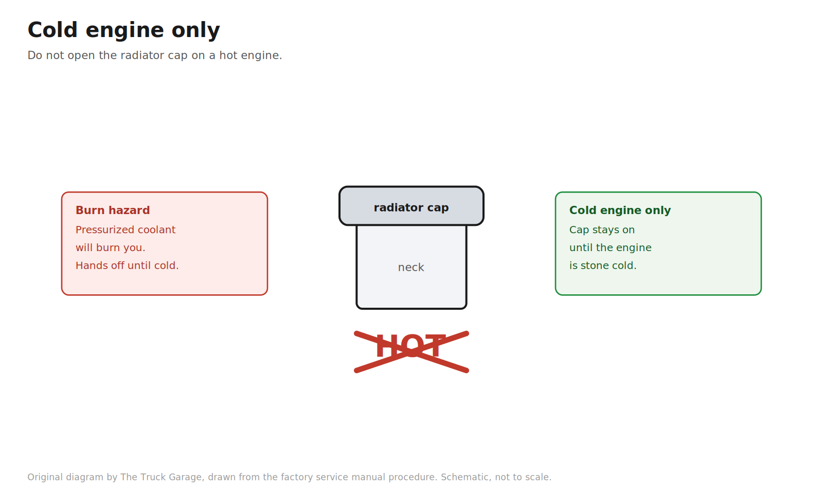
1. Work on a cold engine. Do not remove the radiator cap while the engine is hot. Pressurized coolant will burn you. [manual]
Original diagram by The Truck Garage. Only open the radiator cap on a cold engine. Schematic, not to scale.
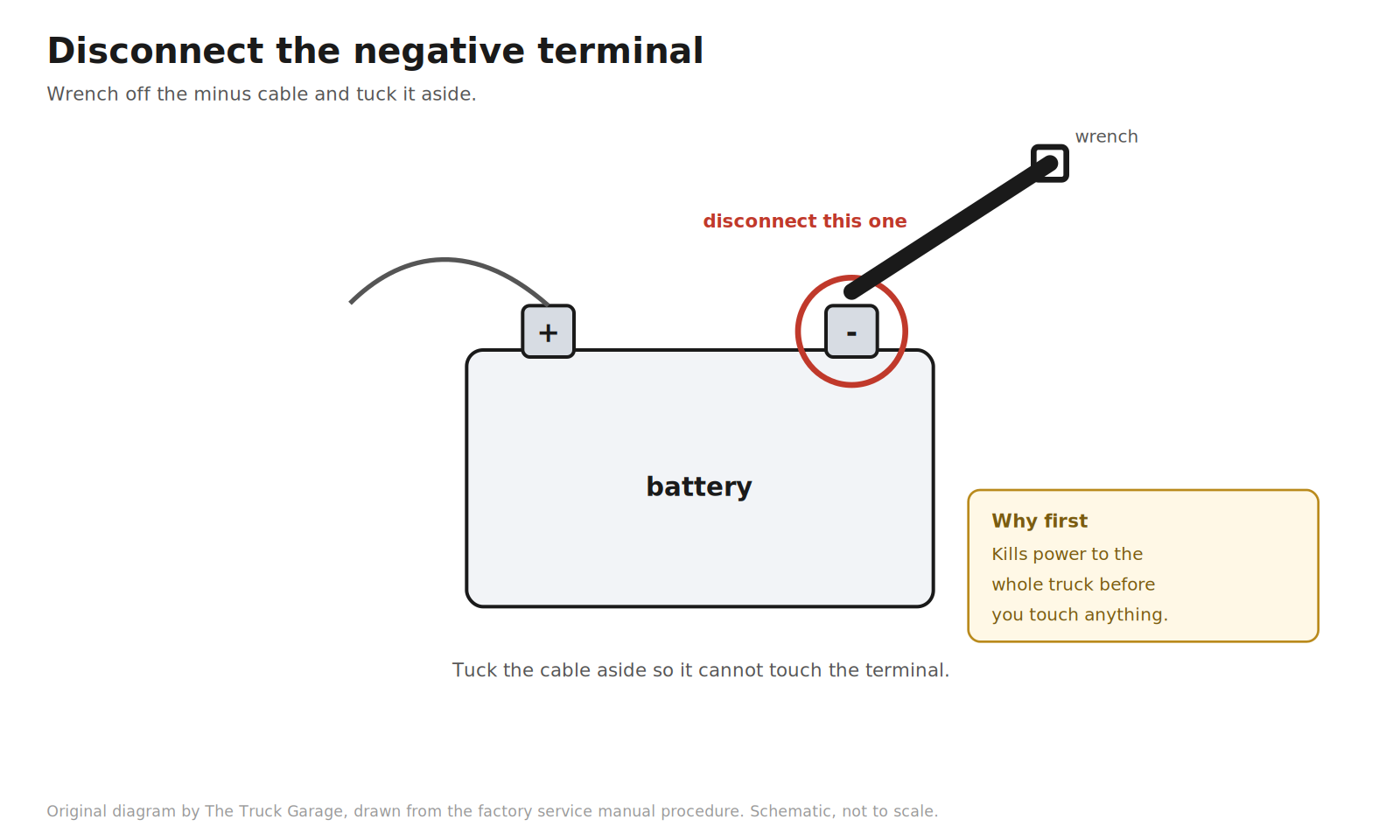
2. Disconnect the battery negative terminal. [manual]
Original diagram by The Truck Garage. Disconnect the battery negative terminal first. Schematic, not to scale.
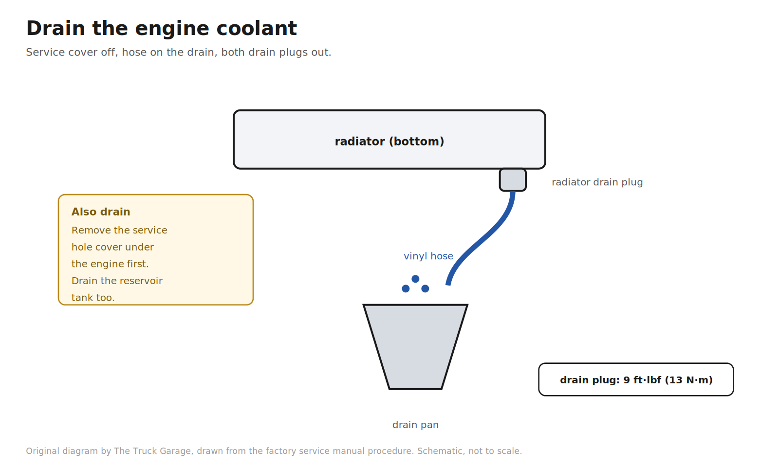
3. Drain the engine coolant. Remove the service hole cover under the engine. Fit a vinyl hose to the radiator drain. Loosen the radiator drain plug and the engine drain plug, and drain the coolant from the radiator. Drain the reservoir tank too. Close both drain plugs when done. The engine drain plug torques to 9 ft·lbf (13 N·m). [manual]
Original diagram by The Truck Garage. Drain the coolant from the radiator and the reservoir. Schematic, not to scale.
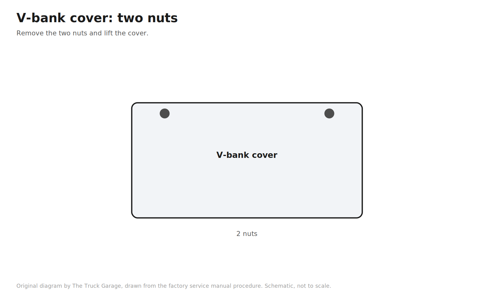
4. Remove the V-bank cover. Two nuts. [manual]
Original diagram by The Truck Garage. The V-bank cover and its two nuts. Schematic, not to scale.
5. Remove the engine room side cover, the side cover LH, and the air cleaner hose. [manual]
Original diagram by The Truck Garage. Side covers and the air cleaner hose removed. Schematic, not to scale.
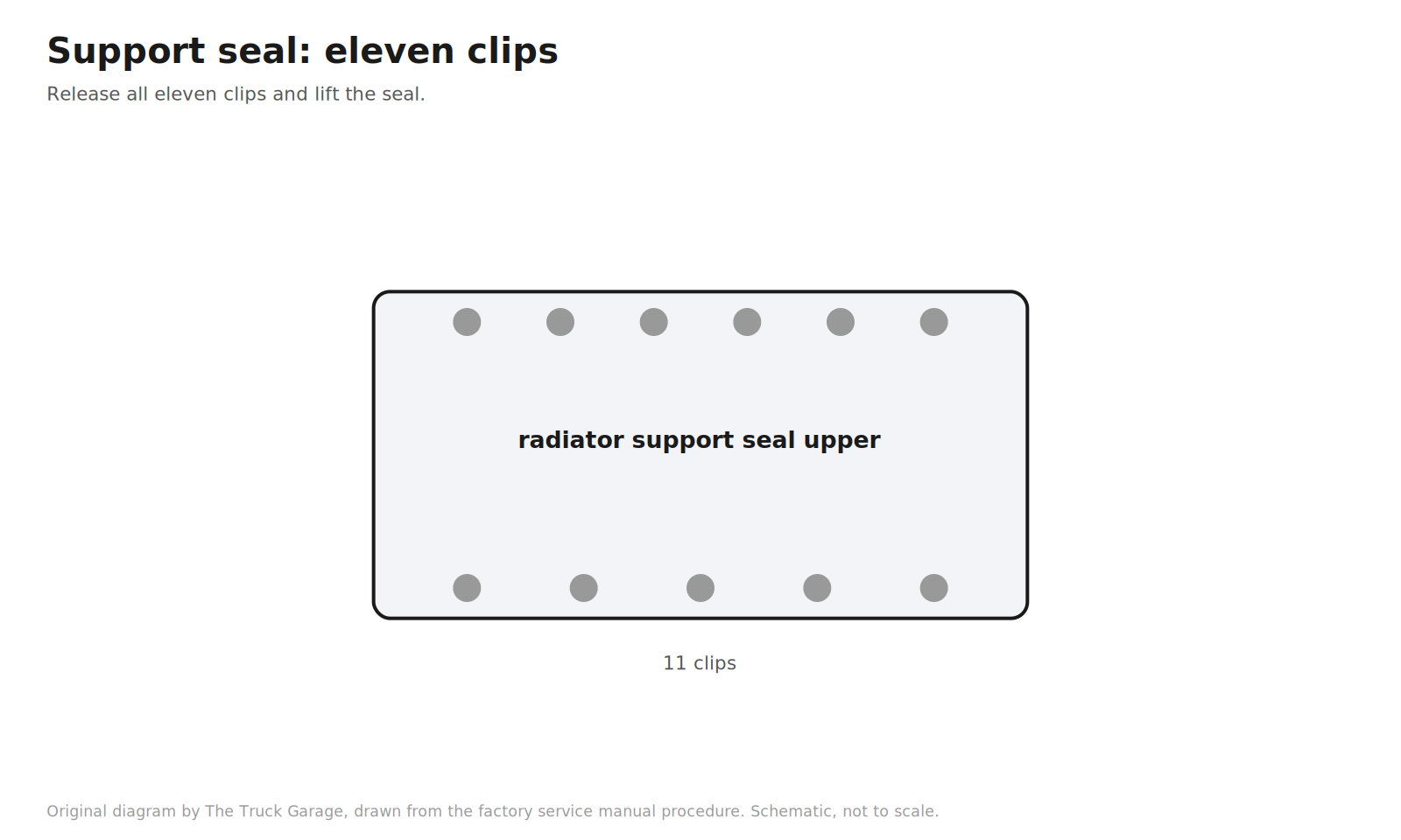
6. Remove the radiator support seal upper. Eleven clips. [manual]
Original diagram by The Truck Garage. The radiator support seal upper with eleven clips. Schematic, not to scale.
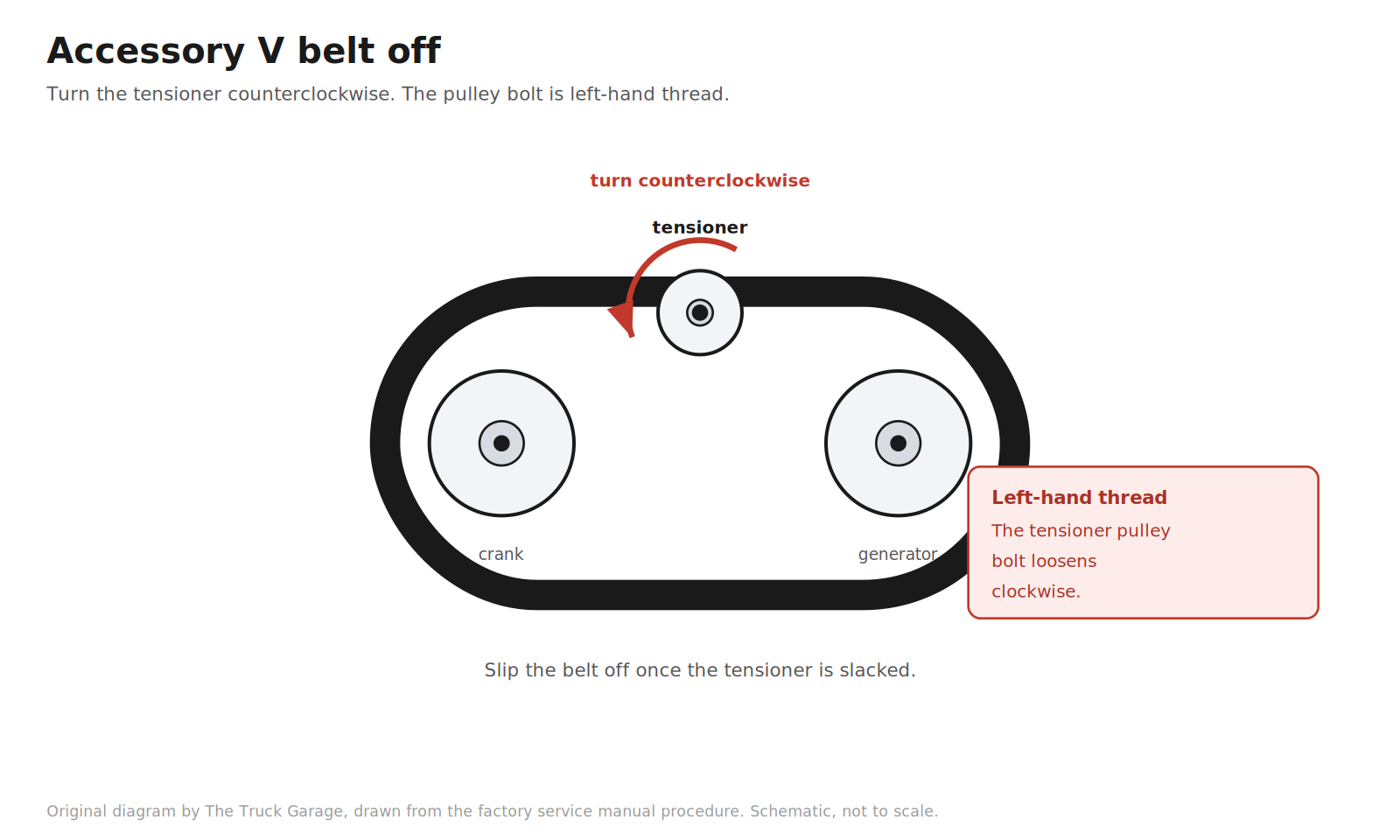
7. Remove the accessory (fan and generator) V belt. Turn the belt tensioner counterclockwise to slack the belt, then slip it off. Warning: the tensioner pulley bolt is left-hand thread. If you are replacing the belt anyway, this is when the old one comes off. [manual]
Original diagram by The Truck Garage. Slacking the accessory belt tensioner to remove the belt. Schematic, not to scale.
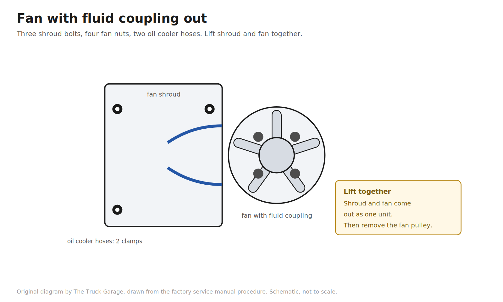
8. Remove the fan with fluid coupling. Unfasten each clip and the two hose clamps, and separate the two oil cooler hoses from the fan shroud. Remove the three bolts holding the fan shroud to the radiator. Remove the four nuts holding the fan with fluid coupling to the engine. Lift the shroud and fan out together. Remove the fan pulley. [manual]
Original diagram by The Truck Garage. Removing the fan with fluid coupling and the fan shroud. Schematic, not to scale.
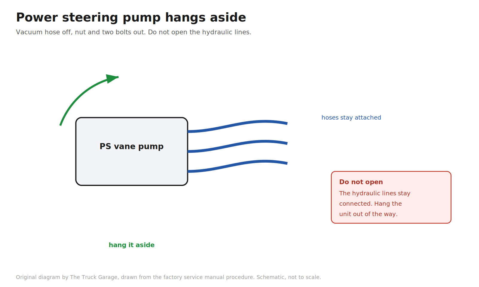
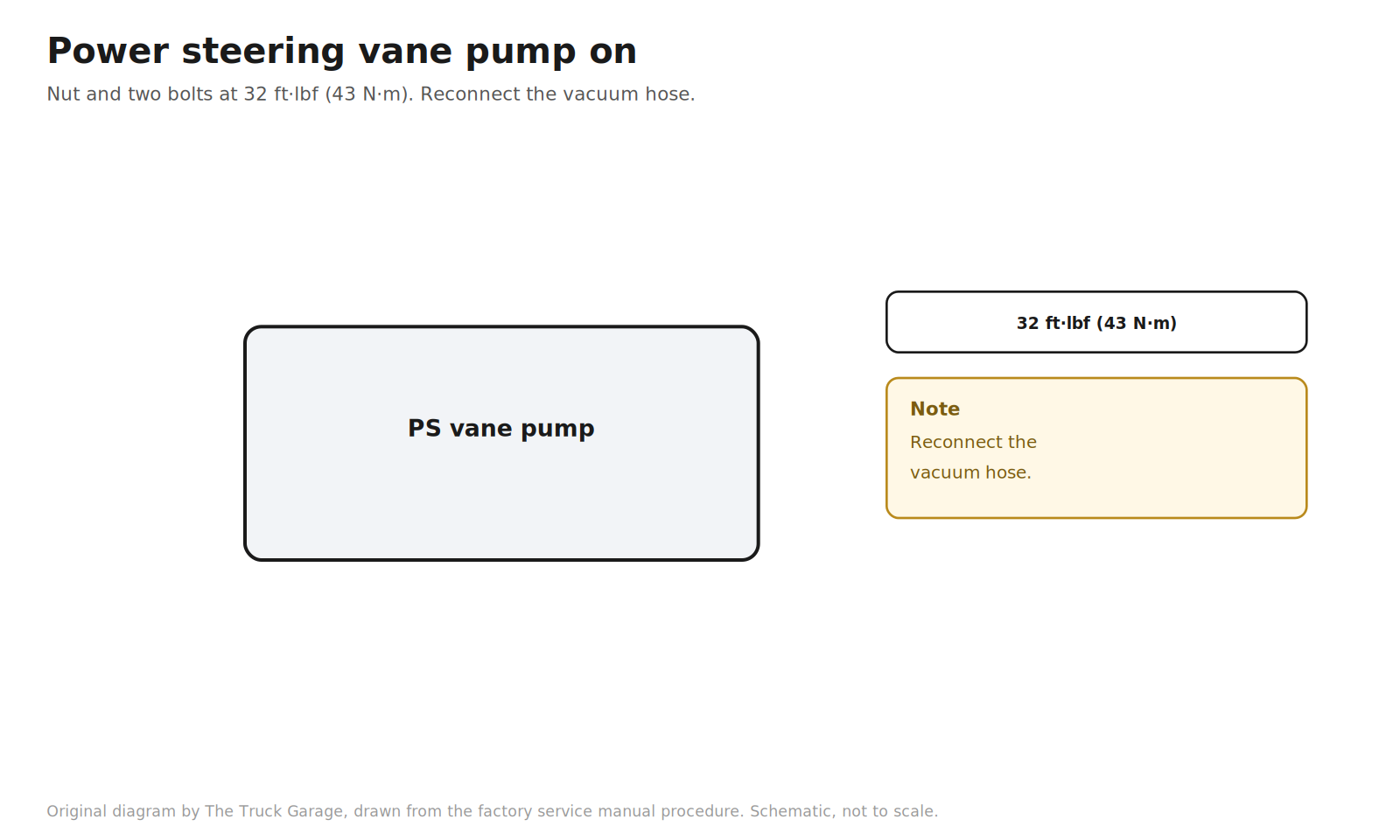
9. Separate the power steering vane pump. Disconnect the vacuum hose. Remove the nut and two bolts. Hang the pump aside with its hoses still attached. Do not open the hydraulic lines. [manual]
Original diagram by The Truck Garage. Hanging the power steering pump aside with its hoses attached. Schematic, not to scale.
10. Remove the generator (alternator). [manual]
Original diagram by The Truck Garage. Removing the generator (alternator). Schematic, not to scale.
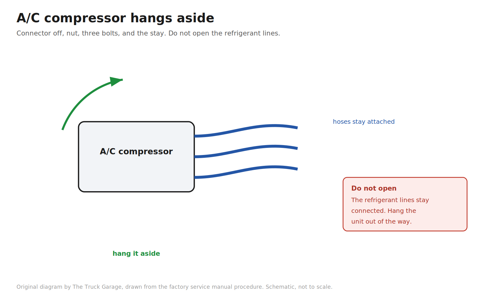
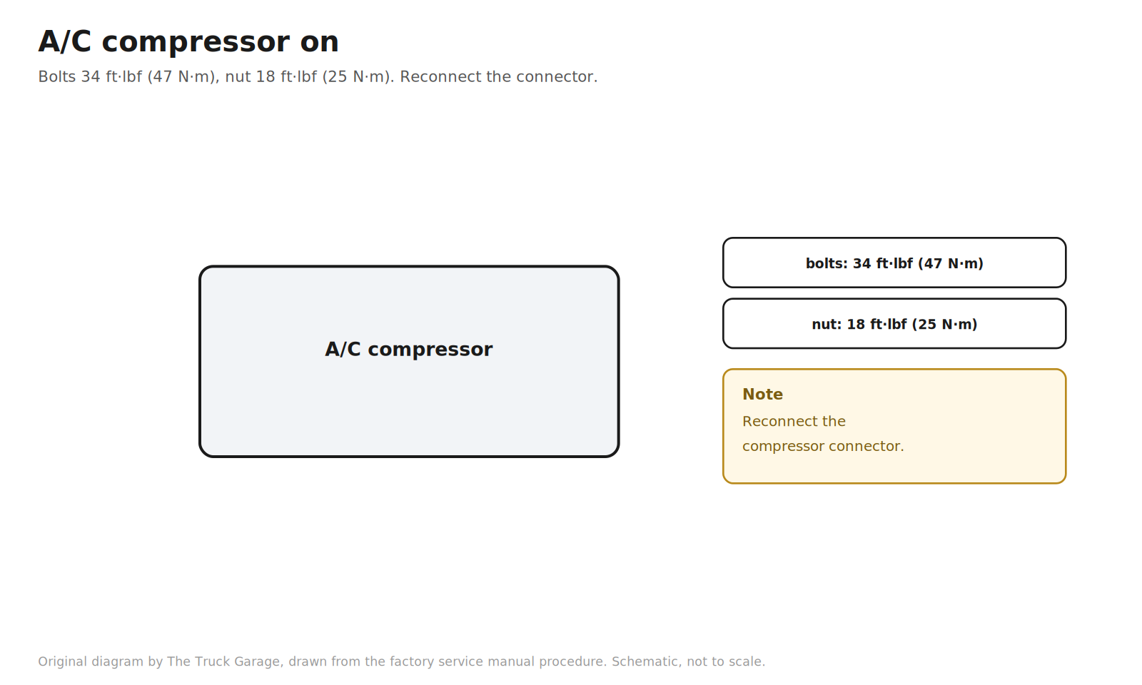
11. Separate the A/C compressor. Disconnect the compressor connector. Remove the nut, three bolts, and the compressor stay. Hang the compressor aside with its hoses still attached. Do not open the refrigerant lines. [manual]
Original diagram by The Truck Garage. Hanging the A/C compressor aside with its hoses attached. Schematic, not to scale.
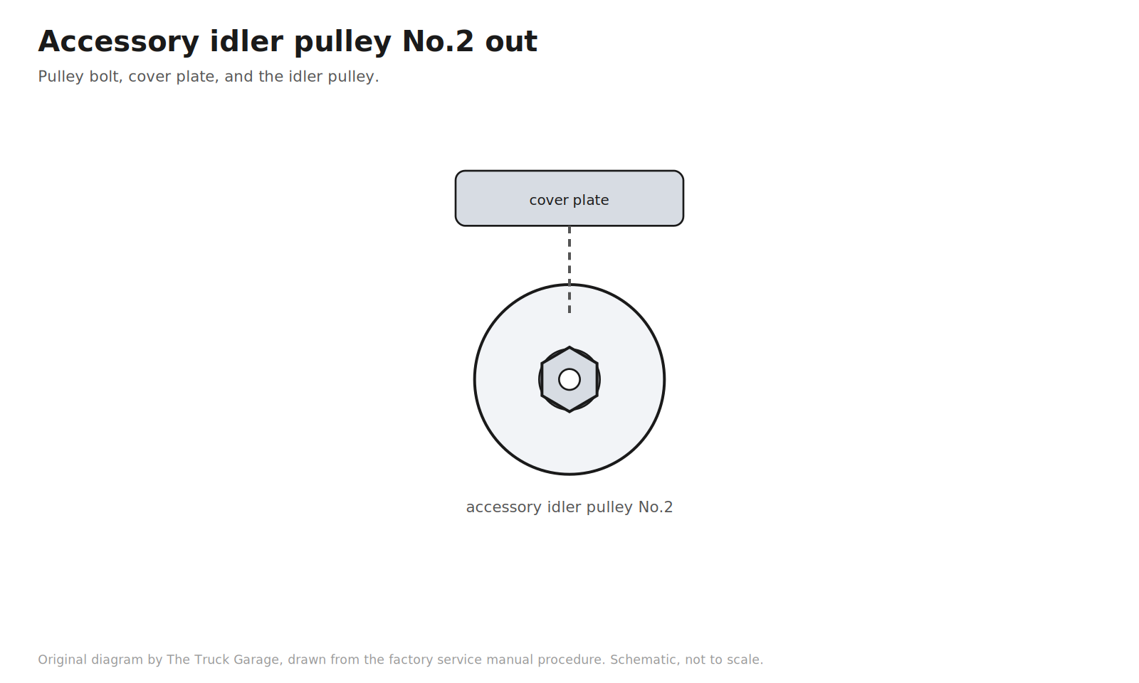
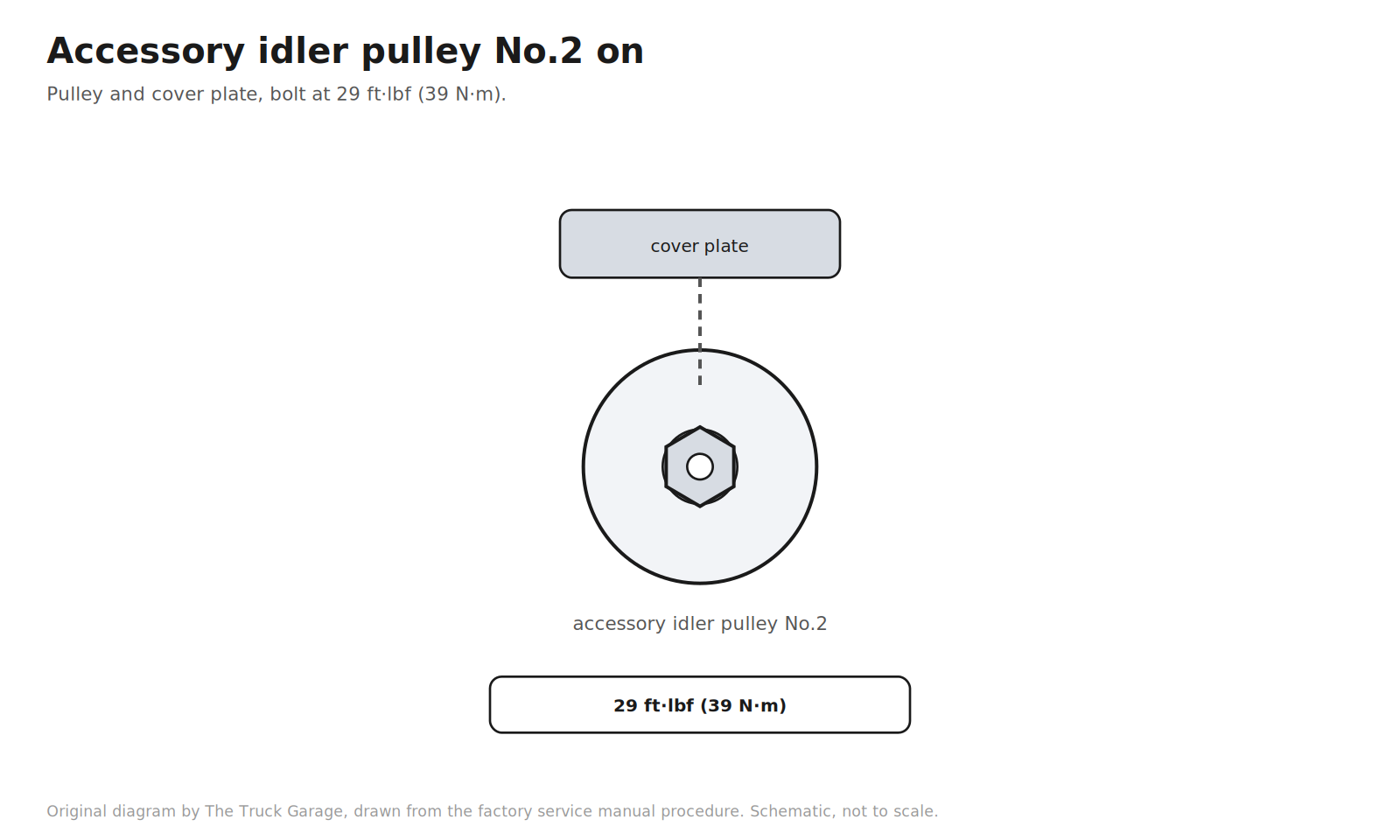
12. Remove the accessory idler pulley No.2. Remove the pulley bolt, the cover plate, and the idler pulley. [manual]
Original diagram by The Truck Garage. Removing accessory idler pulley No.2. Schematic, not to scale.
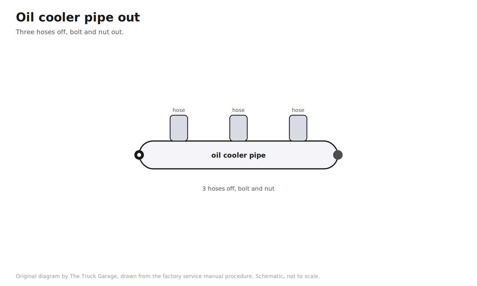
13. Remove the oil cooler pipe. Disconnect the three hoses. Remove the bolt and nut. [manual]
Original diagram by The Truck Garage. Removing the oil cooler pipe. Schematic, not to scale.
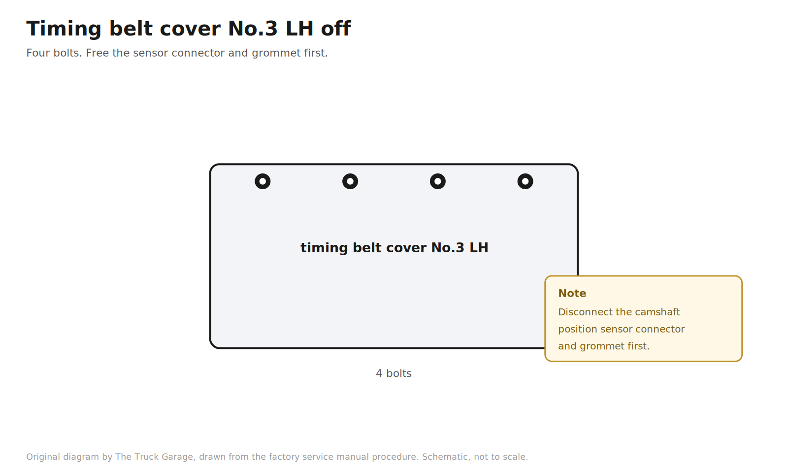
14. Remove the timing belt cover No.3 LH. Remove the grommet and separate the camshaft position sensor connector from the cover. Remove the four bolts and the cover. [manual]
Original diagram by The Truck Garage. Timing belt cover No.3 LH with four bolts and the sensor connector note. Schematic, not to scale.
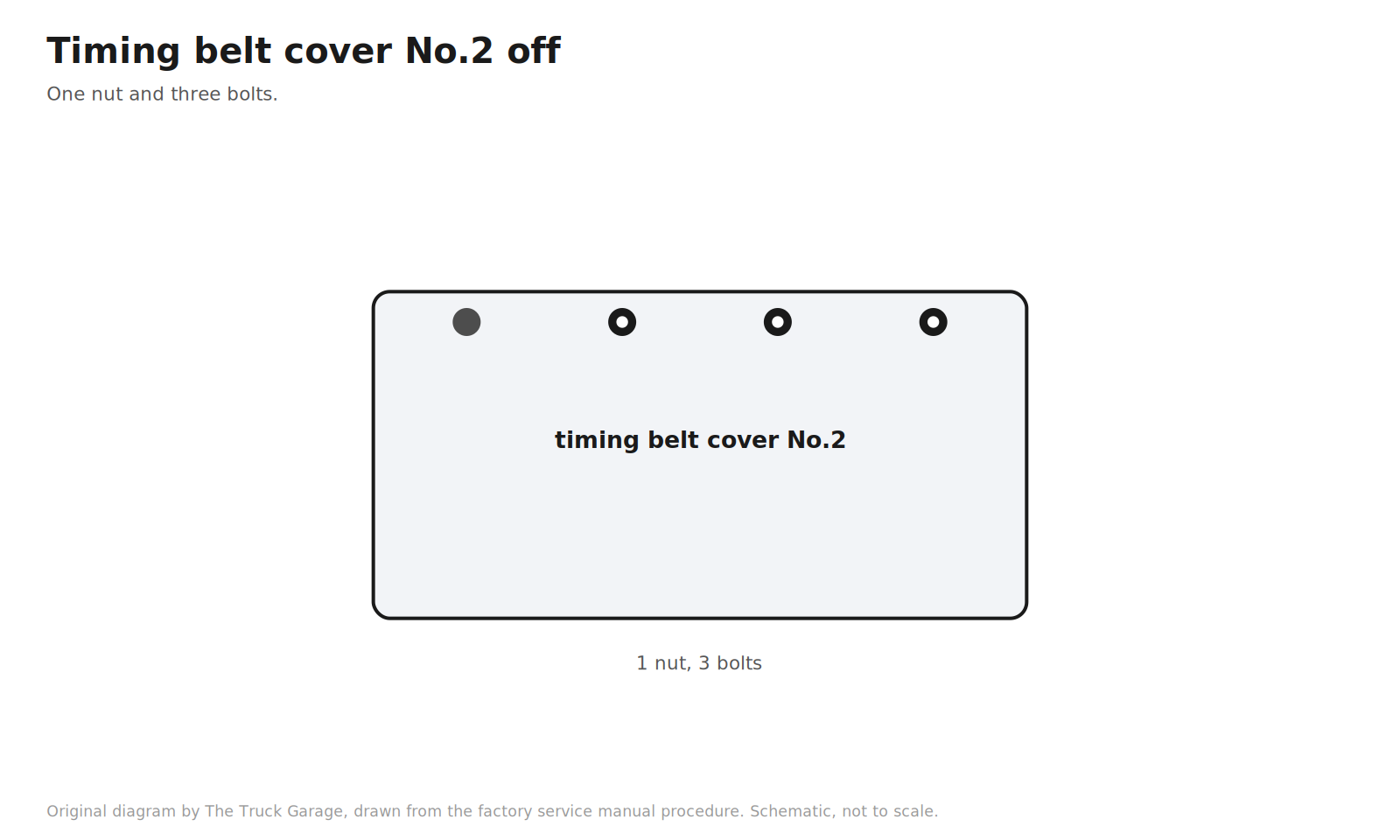
15. Remove the timing belt cover No.2. Remove the nut and three bolts. [manual]
Original diagram by The Truck Garage. Timing belt cover No.2 with one nut and three bolts. Schematic, not to scale.
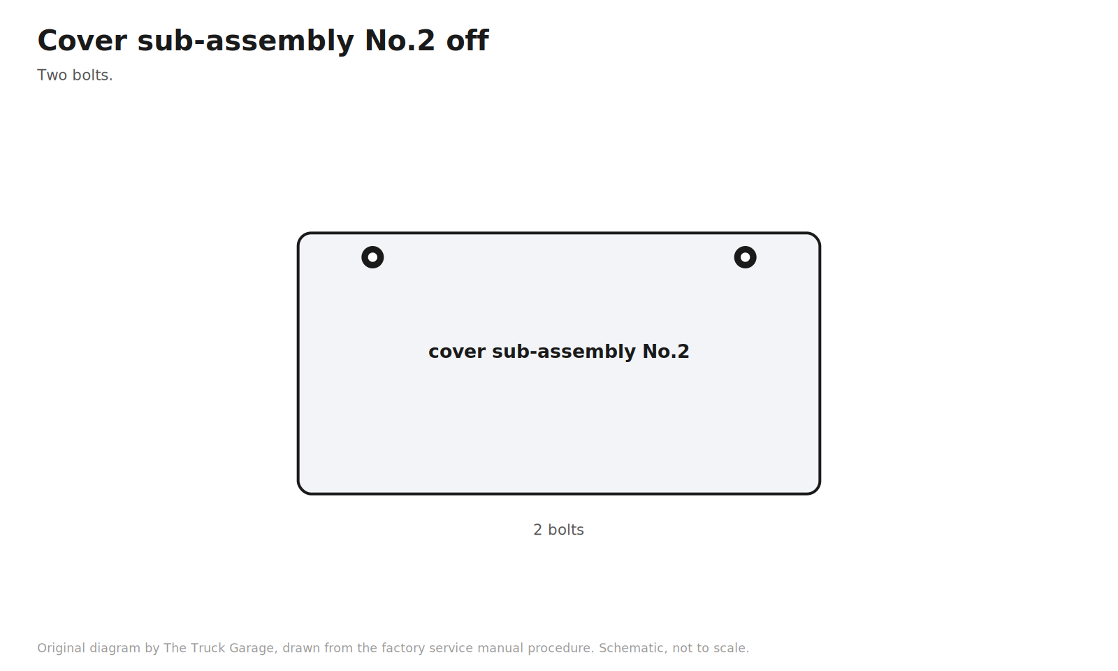
16. Remove the timing belt cover sub-assembly No.2. Two bolts. [manual]
Original diagram by The Truck Garage. Timing belt cover sub-assembly No.2 with two bolts. Schematic, not to scale.
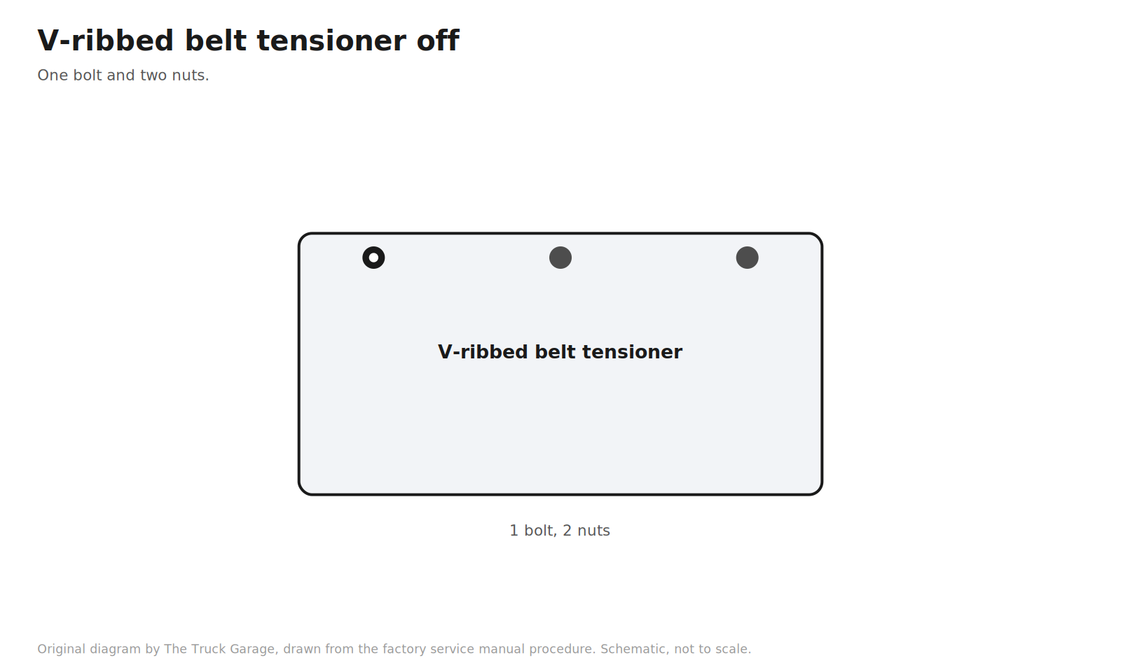
17. Remove the V-ribbed belt tensioner assembly. One bolt and two nuts. [manual]
Original diagram by The Truck Garage. The V-ribbed belt tensioner with one bolt and two nuts. Schematic, not to scale.
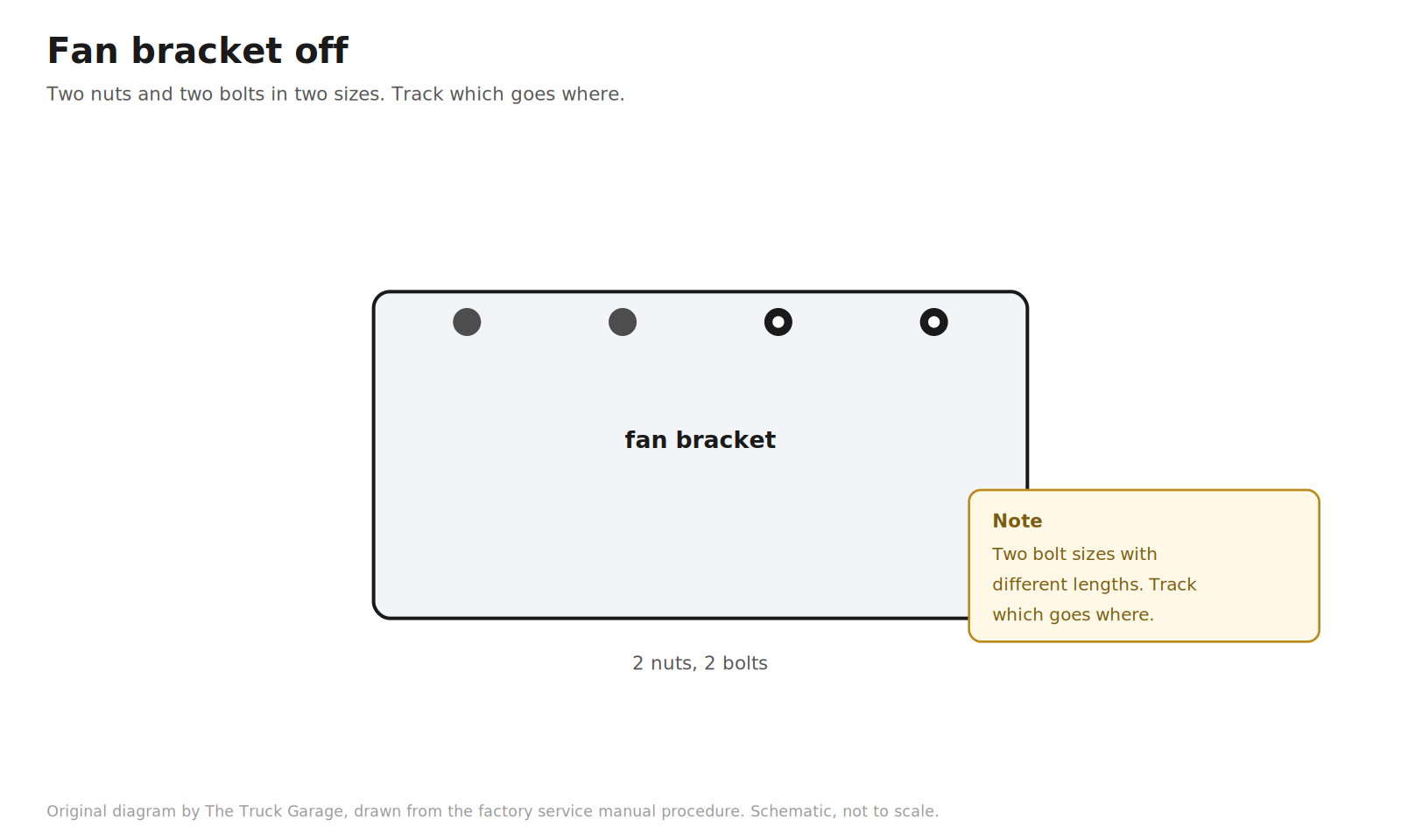
18. Remove the fan bracket. Two nuts and two bolts. Note that the factory uses two bolt sizes here, with different lengths. Keep track of which goes where. [manual]
Original diagram by The Truck Garage. The fan bracket with two nuts and two bolts of different sizes. Schematic, not to scale.
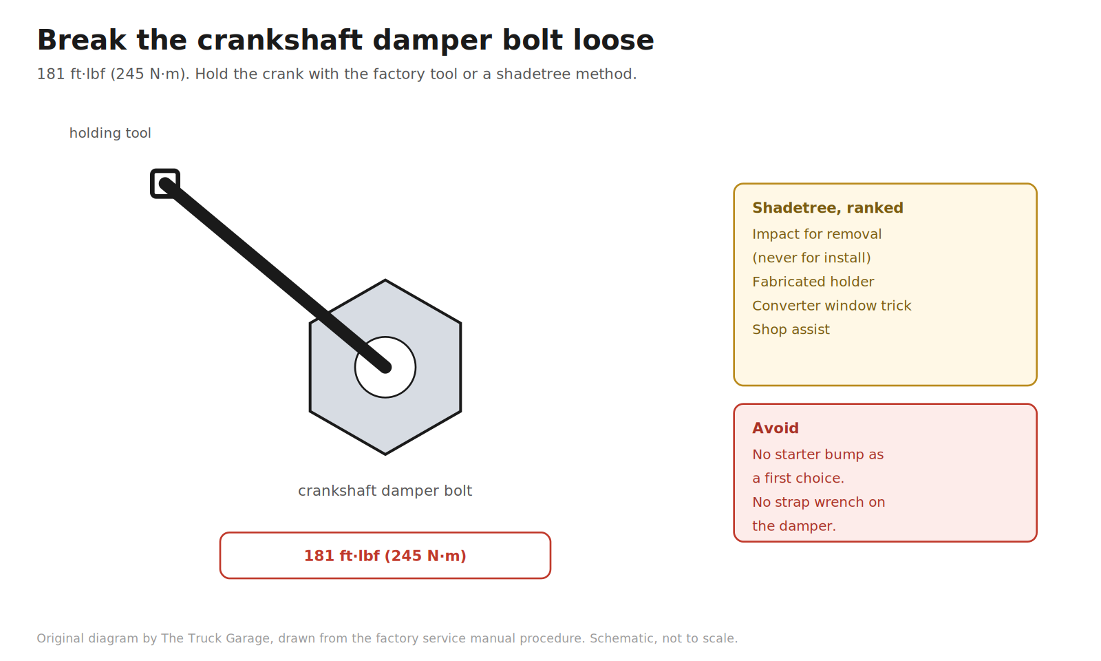
19. Remove the crankshaft damper bolt. This is the gatekeeper of the job. The factory tool is the crankshaft pulley holding tool (SST 09213-70011) with the companion flange holding tool. The bolt is torqued to 181 ft·lbf (245 N·m), so breaking it loose takes real leverage. [manual] Shadetree, ranked by sanity:
Electric impact for removal. A modern 1/2 in brushless impact with 1,000+ ft·lbf of breakaway torque zips the bolt off. Never use the impact to install the bolt. [community]
Fabricated holder. Flat steel bar with two holes drilled to match the pulley bolt holes, braced against the ground or frame. Cheap, controlled, safe if built stout. [community]
Torque converter window trick. Pull the transmission inspection cover, seat a deep socket on a torque converter bolt, and rotate until it jams against the bell housing. Free. Keep the socket straight and fully seated. [community]
Shop assist. Have a shop crack the bolt loose, drive home gently, and do the job. Have them torque it to spec afterward if you cannot. [community]
Do not lead with the starter bump. Breaker bar against the frame, bump the starter. Owners have snapped 1/2 in breaker bars doing this. Last resort only. [community]
Do not use a strap wrench on the damper. It can damage the pulley. [community]
Original diagram by The Truck Garage. Breaking the crankshaft damper bolt loose with the holding tool. Schematic, not to scale.
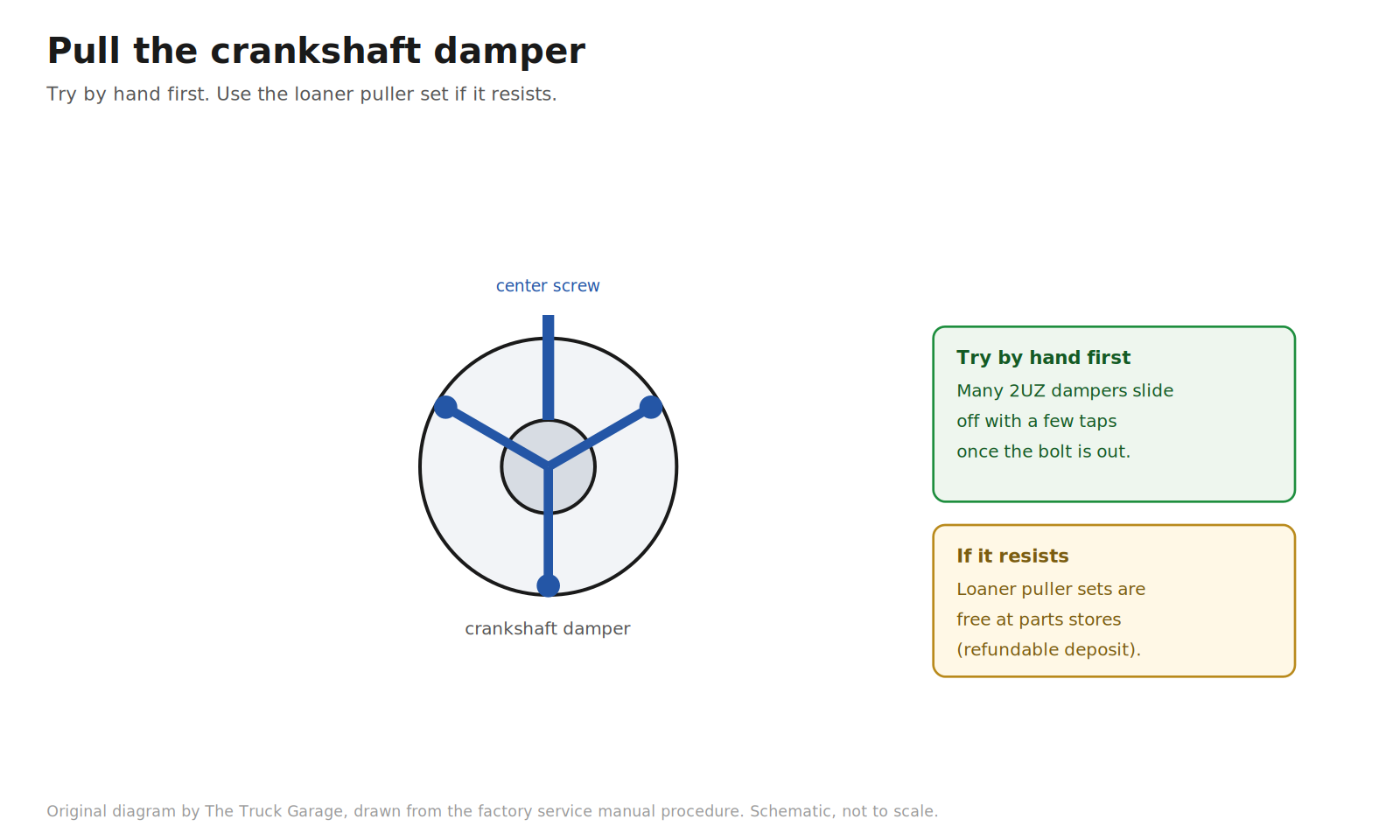
20. Pull the crankshaft damper. The factory puller is SST 09950-50013. [manual] Shadetree: parts stores loan harmonic balancer puller sets free with a refundable deposit. Many owners report the 2UZ damper slides off by hand with a few taps once the bolt is out, so try that before rigging the puller. [community]
Original diagram by The Truck Garage. Pulling the crankshaft damper, by hand or with a puller. Schematic, not to scale.
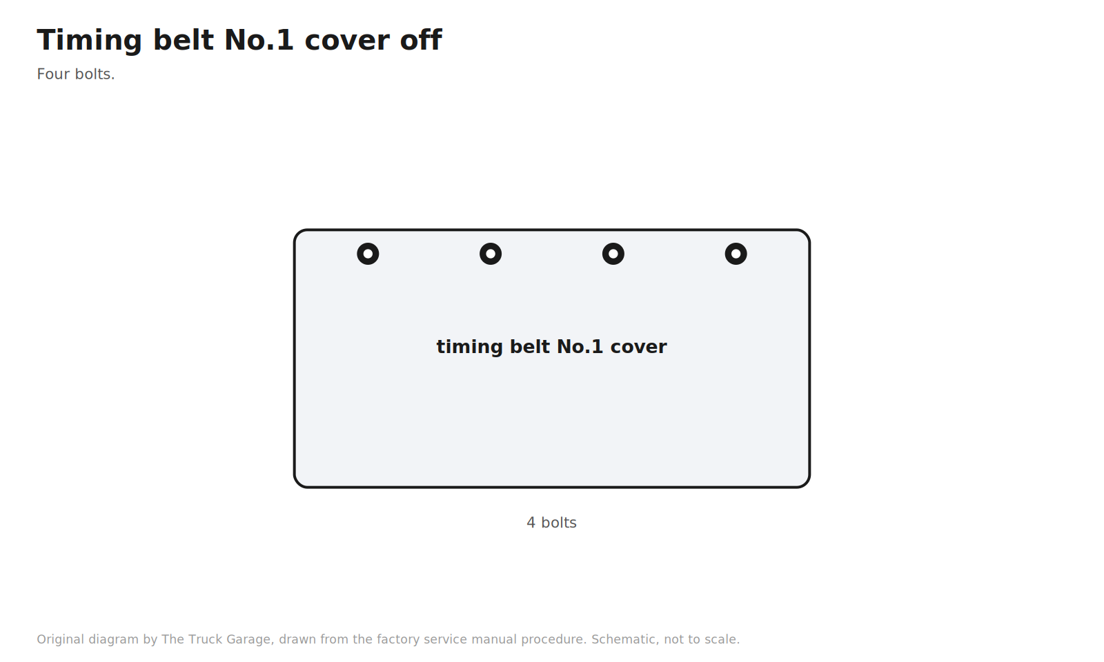
21. Remove the timing belt No.1 cover. Four bolts. [manual]
Original diagram by The Truck Garage. Timing belt No.1 cover with four bolts. Schematic, not to scale.
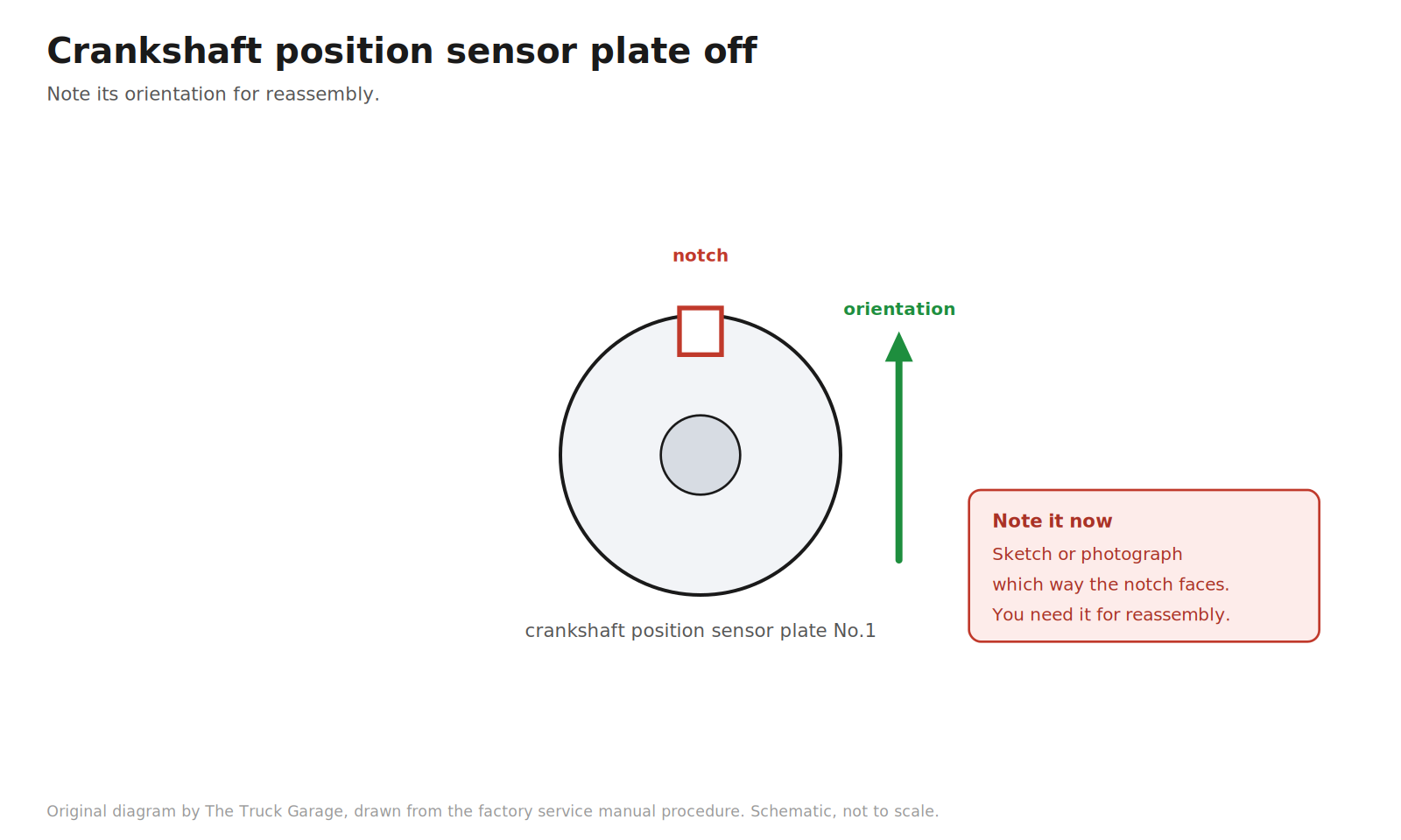
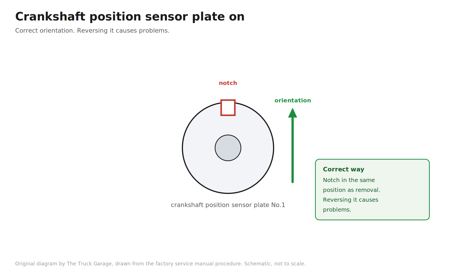
22. Remove the crankshaft position sensor plate No.1. Note its orientation for reassembly. [manual]
Original diagram by The Truck Garage. The crankshaft position sensor plate and its orientation notch. Schematic, not to scale.
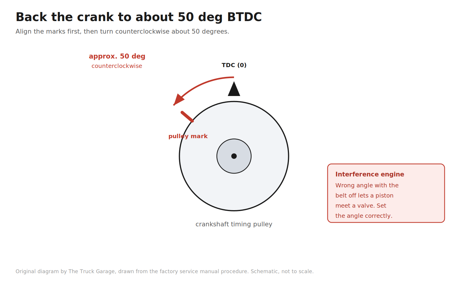
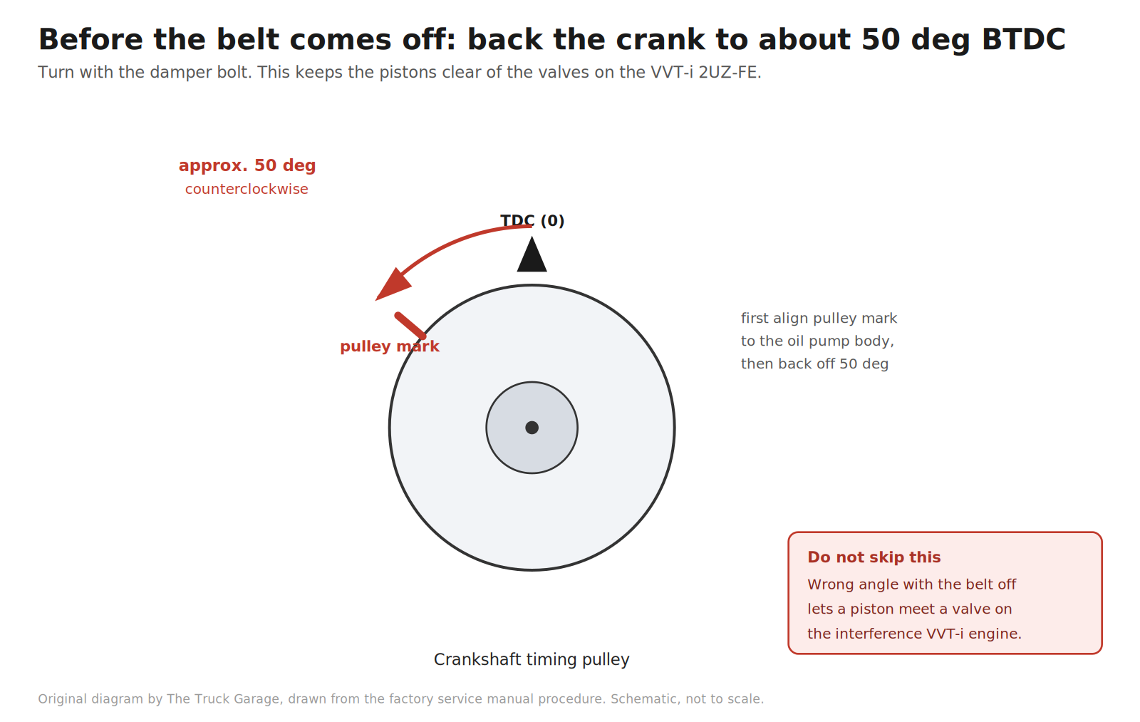
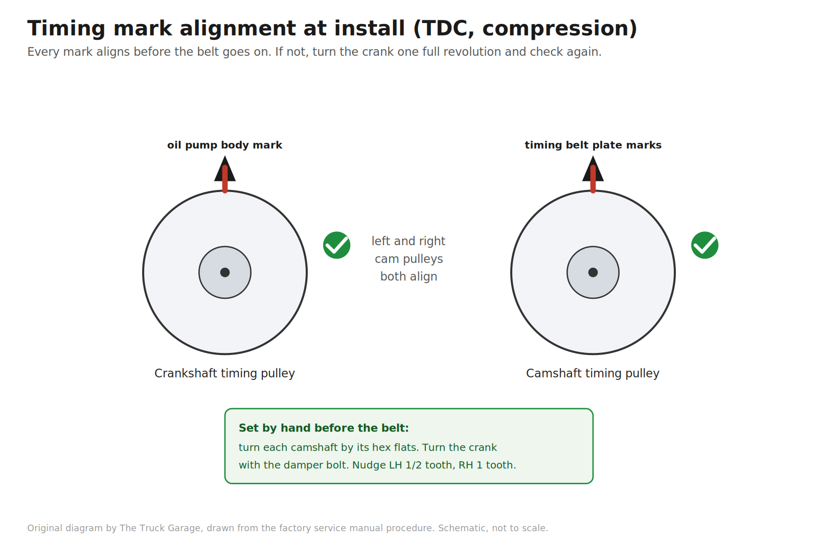
23. Set the crankshaft to approximately 50 degrees before top dead center. This is the interference-engine safety step. Turn the crankshaft with the damper bolt to align the timing marks of the crankshaft timing pulley with the oil pump body. Check that the timing marks of the camshaft timing pulleys align with the timing belt plates. If they do not, turn the crankshaft one full revolution (360 degrees) and check again. Then turn the crankshaft counterclockwise approximately 50 degrees. [manual] Warning: with the belt disengaged, having the crankshaft at the wrong angle can let a piston head contact a valve head when the camshaft timing pulley is disturbed. Set the angle correctly. [manual]
Original diagram by The Truck Garage. Backing the crankshaft to about 50 degrees before top dead center. Schematic, not to scale.Original diagram by The Truck Garage. Back the crank to about 50 deg BTDC before the belt comes off. Schematic, not to scale.
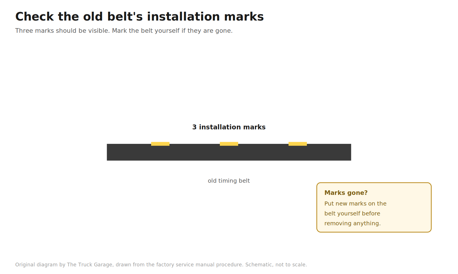
24. If you are reusing the old belt, check its installation marks. Turn the crankshaft and confirm three installation marks on the belt. If the marks have disappeared, put new marks on the belt before removing anything. In practice you are installing a new belt from the kit, so this step is just confirming the old belt’s marks for reference. [manual]
Original diagram by The Truck Garage. Checking the three installation marks on the old timing belt. Schematic, not to scale.
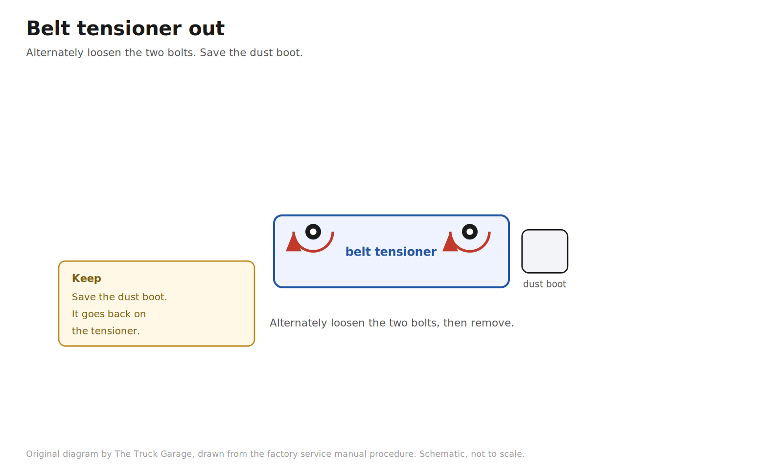
25. Remove the belt tensioner. Alternately loosen the two bolts, then remove the bolts, the tensioner, and the dust boot. [manual]
Original diagram by The Truck Garage. Removing the belt tensioner and its dust boot. Schematic, not to scale.
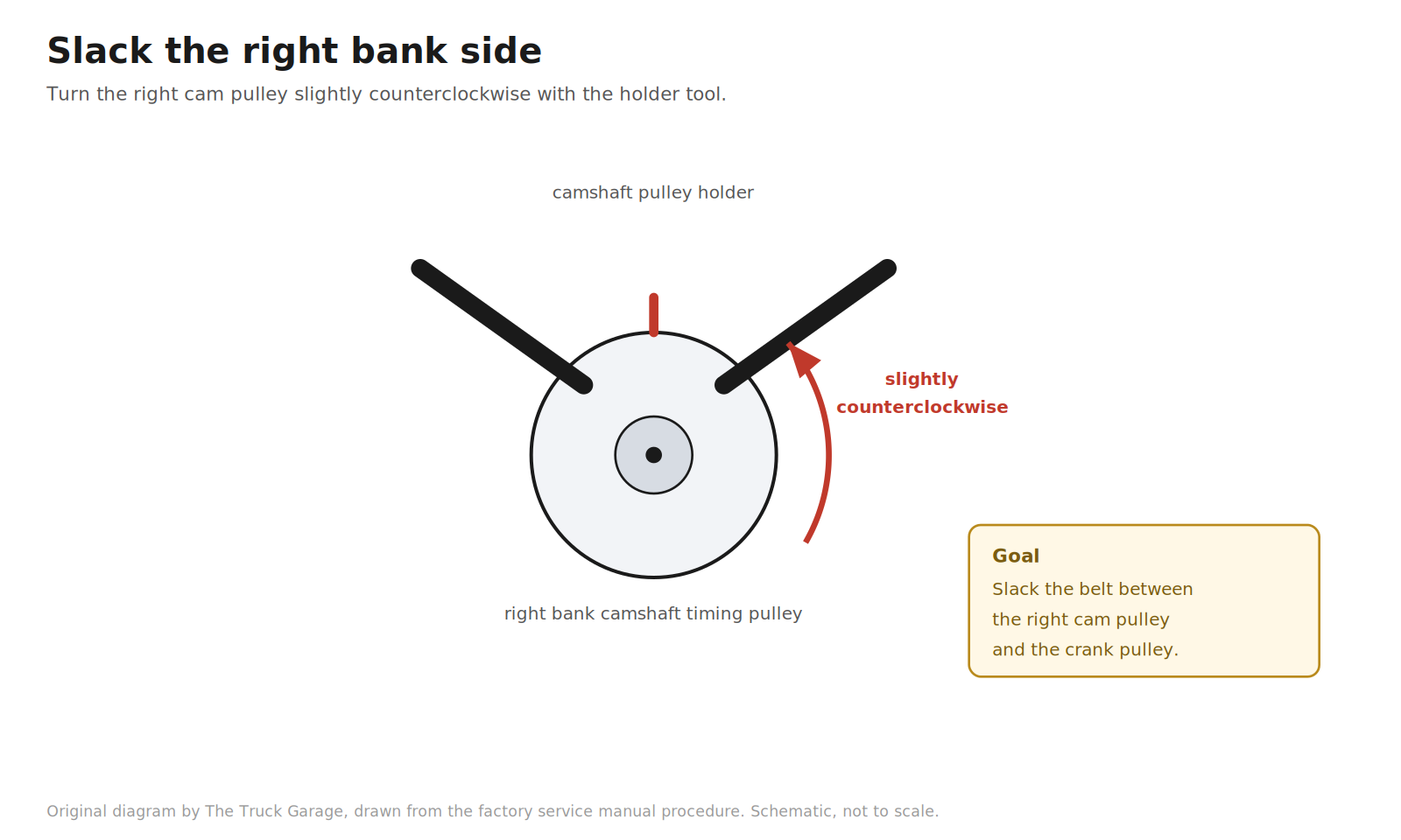
26. Slack the right bank side. Using the camshaft pulley holder (SST 09960-10010), turn the right bank camshaft timing pulley slightly counterclockwise. This loosens the belt tension between the right cam pulley and the crank pulley. [manual]
Original diagram by The Truck Garage. Slacking the belt with the camshaft pulley holder. Schematic, not to scale.
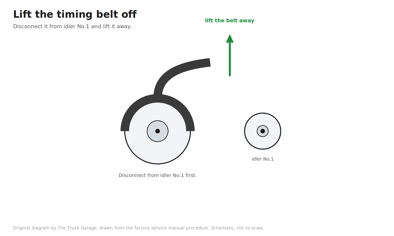
27. Remove the timing belt. Disconnect the belt from timing belt idler No.1 and lift the belt off. [manual]
Original diagram by The Truck Garage. Lifting the timing belt off the pulleys. Schematic, not to scale.
Belt and pump replacement
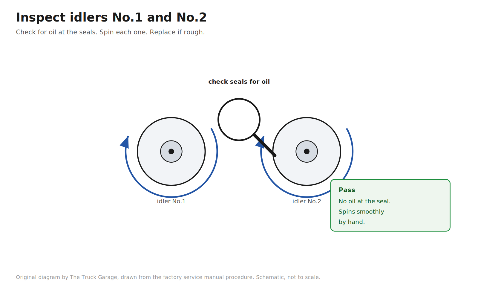
28. Inspect the timing belt idlers No.1 and No.2. Visually check the seal area of each idler pulley for oil leakage. Spin each idler by hand and confirm it turns smoothly. Replace any idler that leaks or feels rough. New idlers come in the kit. [manual]
Original diagram by The Truck Garage. Inspecting the timing belt idlers for leaks and smooth spin. Schematic, not to scale.
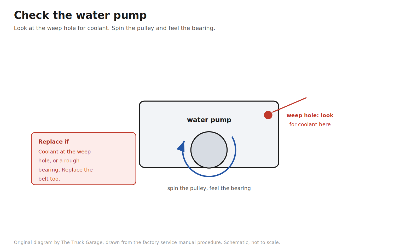
29. Check the water pump. Look at the pump’s air hole and drain (weep) hole for coolant leakage. Turn the pulley and confirm the bearing moves smoothly. If leakage is found, replace the water pump and the timing belt. If the bearing feels rough, replace the pump. [manual]
Original diagram by The Truck Garage. Checking the water pump weep hole and bearing. Schematic, not to scale.
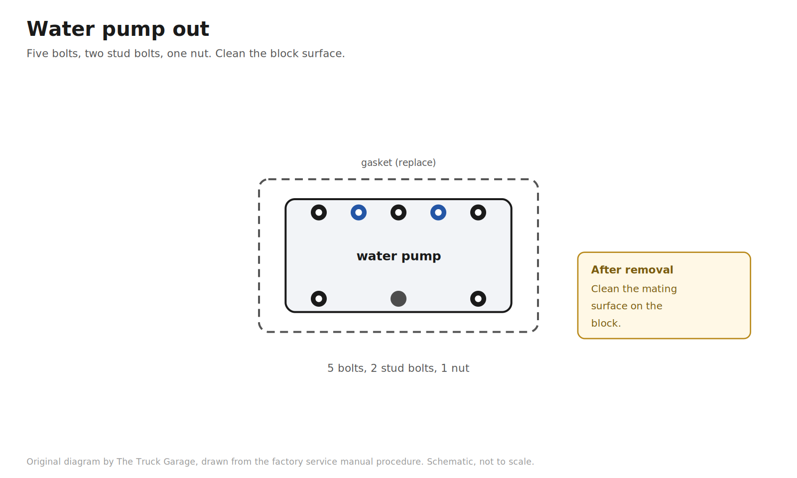
30. Remove the water pump. Remove the five bolts, two stud bolts, nut, water pump, and gasket. Clean the mating surface on the block. [manual]
Original diagram by The Truck Garage. Removing the water pump: five bolts, two studs, one nut. Schematic, not to scale.
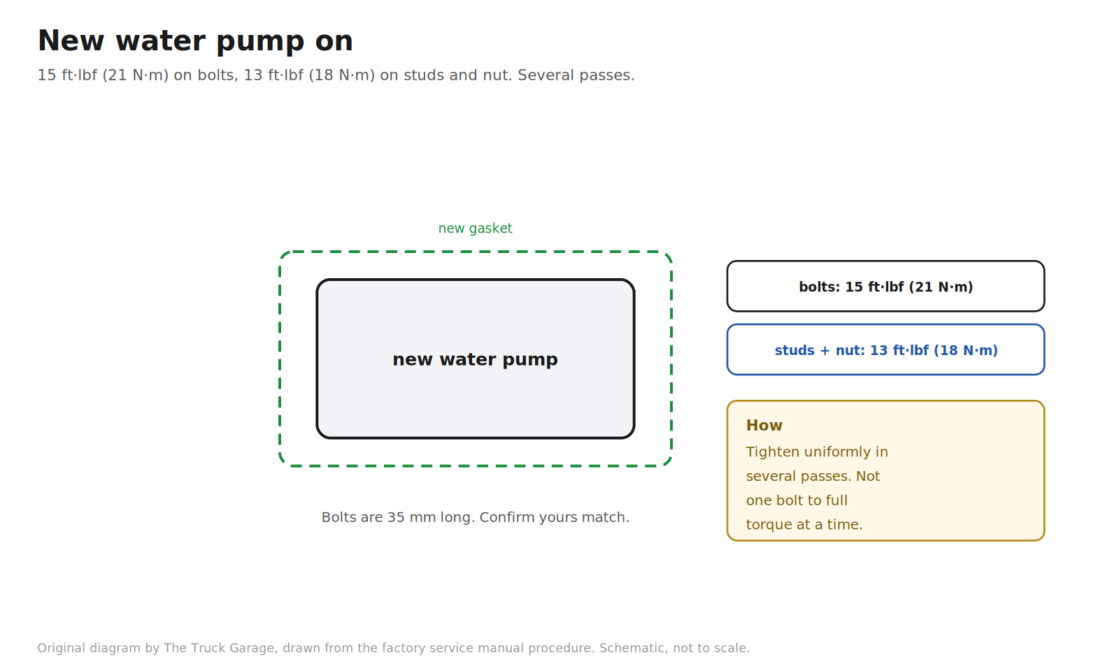
31. Install the new water pump. Fit the new gasket and the pump with the five bolts, two stud bolts, and nut. Tighten them uniformly in several passes, not one bolt at a time to full torque. Torque: bolts 15 ft·lbf (21 N·m); stud bolts and nut 13 ft·lbf (18 N·m). The factory notes the bolts are 35 mm long, so confirm your bolts match. [manual]
Original diagram by The Truck Garage. Installing the new water pump with the correct torques. Schematic, not to scale.
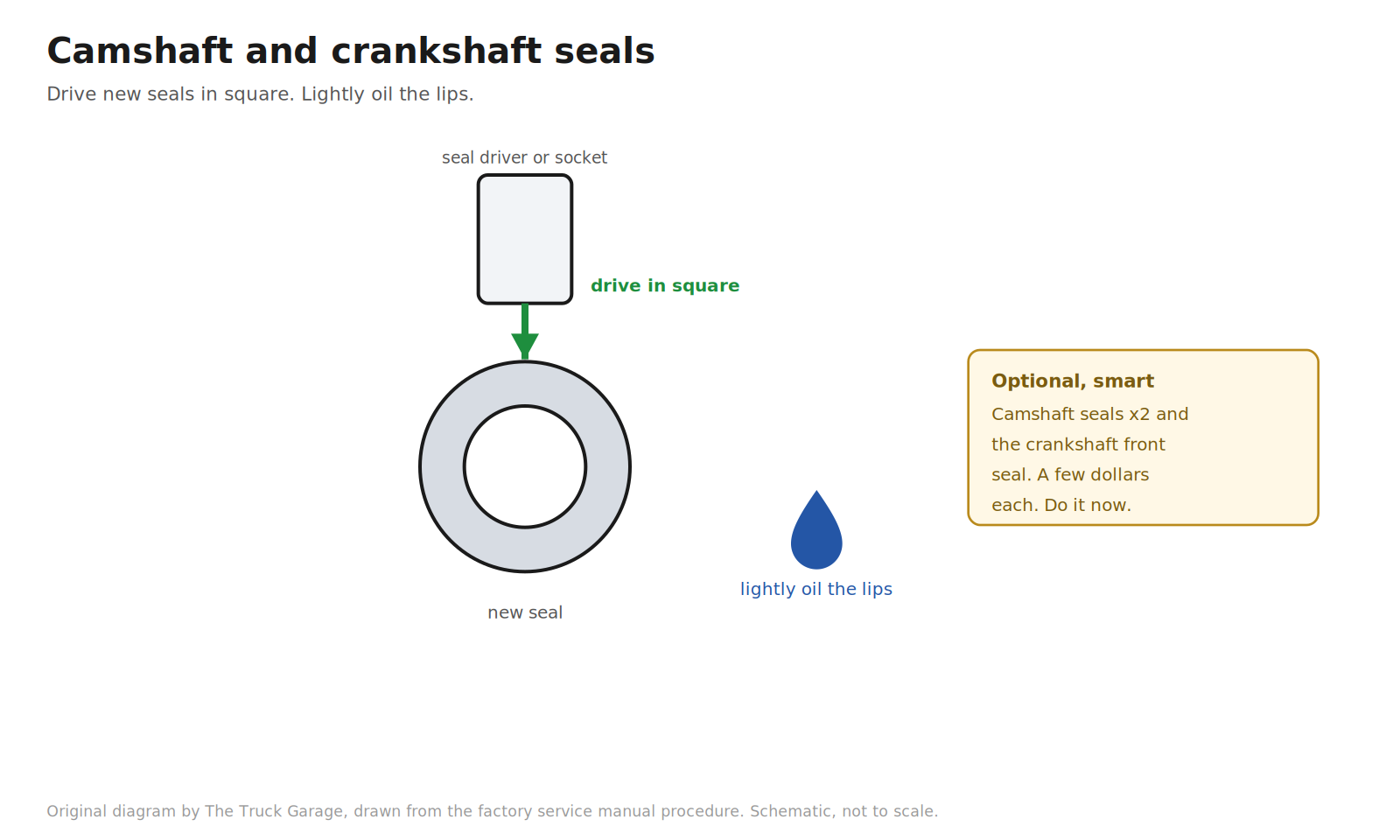
32. Replace the camshaft seals and crankshaft front seal (optional, recommended). With the belt off and the pulleys exposed, the seals are right there. Pull the old seals, drive the new ones in square with a seal driver or a suitable socket, and lightly oil the seal lips. They cost a few dollars each and you do not want to open this up again for a five dollar seal. [community]
Original diagram by The Truck Garage. Replacing the camshaft and crankshaft seals. Schematic, not to scale.
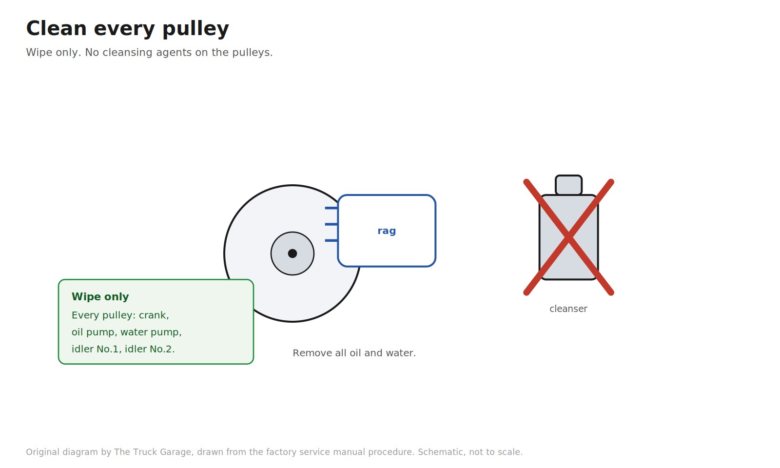
33. Clean every pulley. Wipe the crankshaft pulley, oil pump pulley, water pump pulley, idler No.1, and idler No.2 to remove all oil and water. The factory is explicit: wipe only. Do not use any cleansing agent on the pulleys. [manual]
Original diagram by The Truck Garage. Wiping every pulley clean, with cleansers crossed out. Schematic, not to scale.
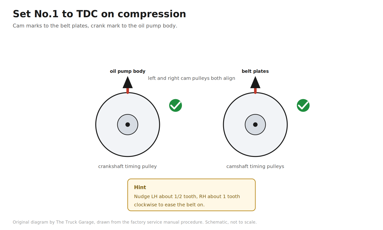
34. Set No.1 cylinder to top dead center on compression. Turn each camshaft by its hexagonal portion to align the timing marks of the camshaft timing pulleys with the timing belt plates. The manual’s hint: turning the left bank pulley about half a tooth clockwise and the right bank pulley about one tooth clockwise makes the belt installation easier. Then turn the crankshaft with the damper bolt to align the timing marks of the crankshaft timing pulley with the oil pump body. [manual]
Original diagram by The Truck Garage. Aligning all timing marks at top dead center on compression. Schematic, not to scale.Original diagram by The Truck Garage. Timing mark alignment at TDC on compression, before the belt goes on. Schematic, not to scale.
35. Install the new timing belt, in order. Face the front mark (arrow) on the belt forward. Put the belt on in this sequence, aligning each installation mark on the belt with the timing mark of its pulley: crankshaft timing pulley, idler No.2, left bank camshaft timing pulley, water pump pulley, right bank camshaft timing pulley, idler No.1. [manual]
Original diagram by The Truck Garage. Routing the new timing belt in the factory install order. Schematic, not to scale.Original diagram by The Truck Garage. Belt install order and timing mark positions, drawn from the factory service manual. Schematic, not to scale.Original diagram by The Truck Garage. Align each belt installation mark with its pulley timing mark. Schematic, not to scale.
36. Compress and pin the belt tensioner. Using a press, slowly press the push rod in with 220 to 2,205 lbf of pressure. Align the holes in the push rod and the housing, and pass the 1.27 mm (0.05 in) hex wrench through the holes to hold the push rod in the compressed position. Release the press. Fit the dust boot onto the tensioner. [manual] Shadetree: a large bench vise does the same job as the press. Compress slowly. Do not rush the push rod in. [community]
Original diagram by The Truck Garage. Compressing and pinning the belt tensioner. Schematic, not to scale.
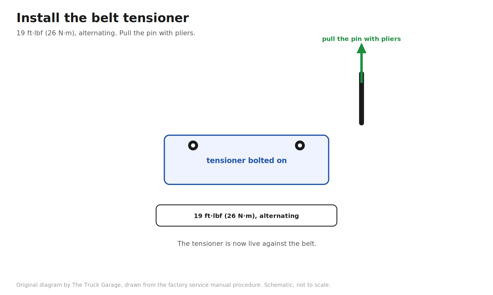
37. Install the belt tensioner. Temporarily install the tensioner with the two bolts, then alternately tighten the bolts to 19 ft·lbf (26 N·m). Using pliers, pull the 1.27 mm hex wrench out. The tensioner is now live against the belt. [manual]
Original diagram by The Truck Garage. Bolting the tensioner on and pulling the pin. Schematic, not to scale.Original diagram by The Truck Garage. Compress the push rod slowly, pin it with a 1.27 mm (0.05 in) hex wrench, then bolt the tensioner on. Schematic, not to scale.
Reassembly
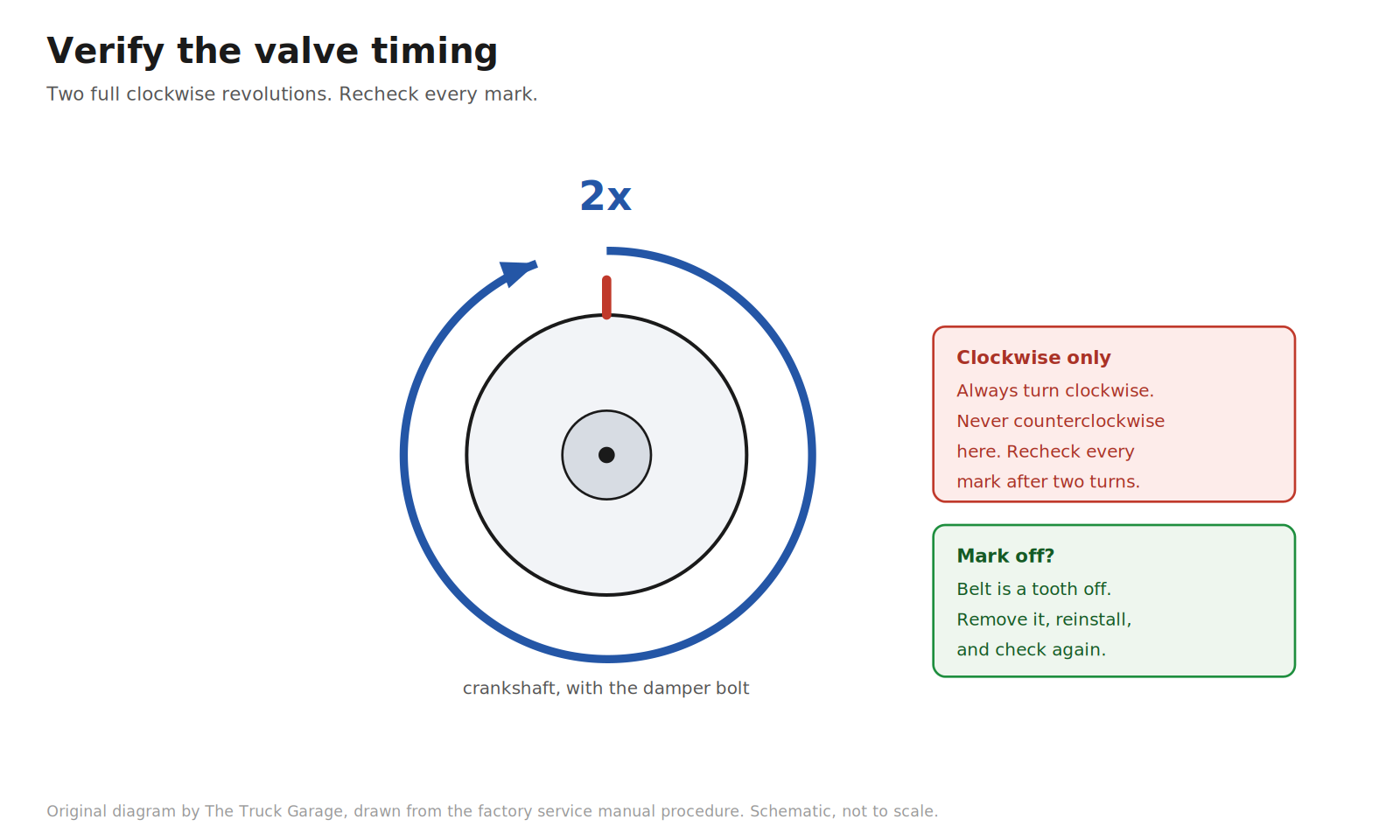
38. Verify the valve timing. Using the crankshaft damper bolt, slowly turn the crankshaft two full revolutions, from TDC back to TDC. Always turn clockwise. Never turn it counterclockwise here. Then check that every pulley’s timing marks still align with their marks. If any mark is off, remove the belt and reinstall it. When the marks are correct, remove the crankshaft damper bolt. [manual]
Original diagram by The Truck Garage. Turning the crankshaft two full clockwise revolutions to verify timing. Schematic, not to scale.
39. Install the crankshaft position sensor plate No.1. Install it in the correct orientation. Reversing it causes problems. [manual]
Original diagram by The Truck Garage. Reinstalling the crankshaft position sensor plate in the correct orientation. Schematic, not to scale.
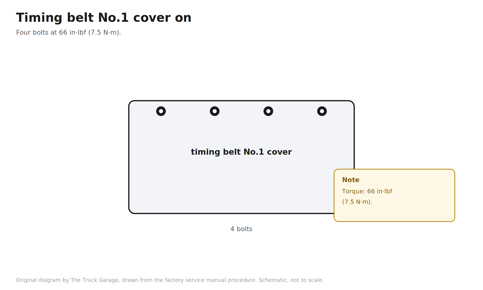
40. Install the timing belt No.1 cover. Four bolts, torqued to 66 in·lbf (7.5 N·m). [manual]
Original diagram by The Truck Garage. Reinstalling timing belt No.1 cover at 66 in·lbf. Schematic, not to scale.
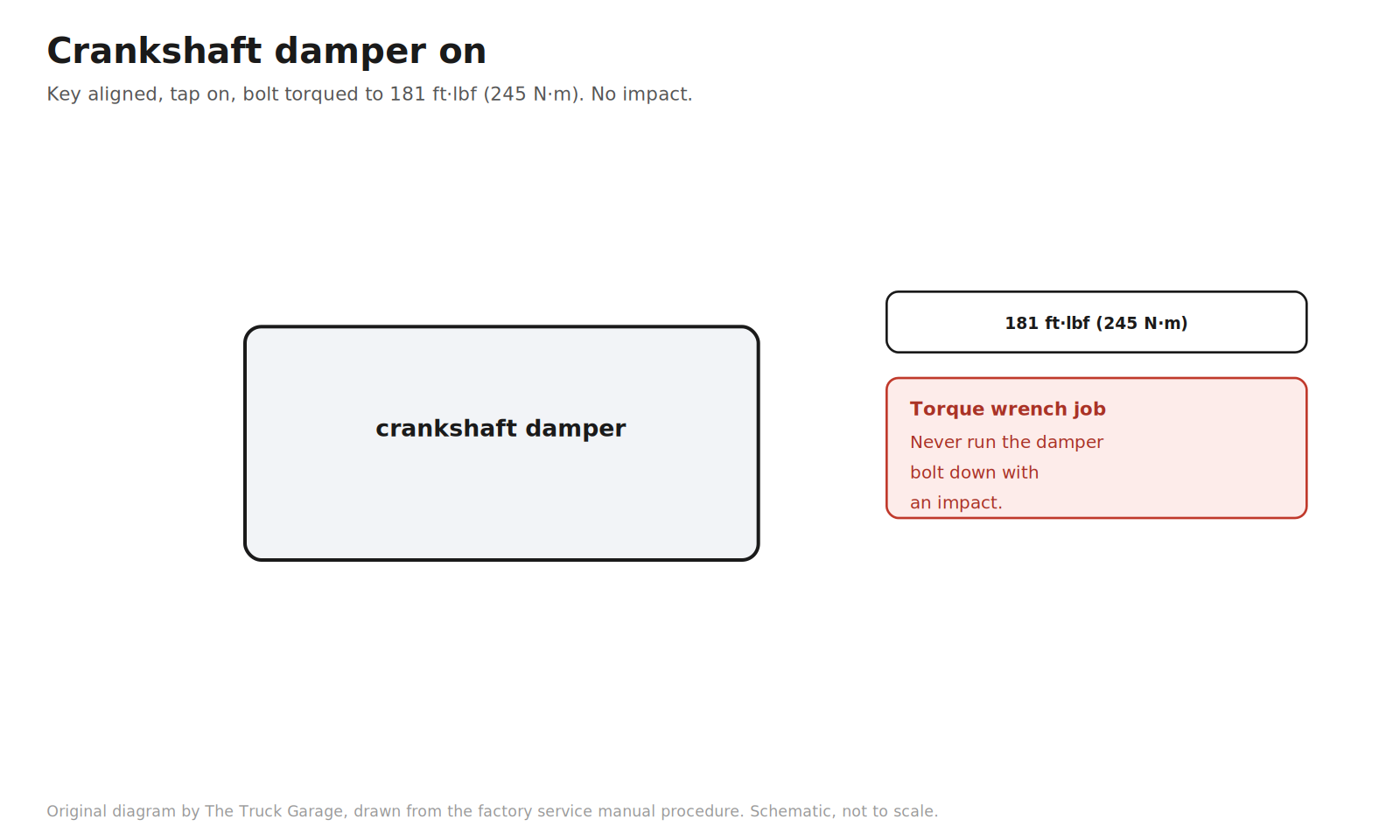
41. Install the crankshaft damper. Align the pulley set key with the key groove of the damper. Tap the damper on with a hammer using the proper driver. Install the damper bolt using the holding tool and torque it to 181 ft·lbf (245 N·m). This is a torque wrench job. Never run the bolt down with an impact. [manual]
Original diagram by The Truck Garage. Installing the crankshaft damper and torquing the bolt. Schematic, not to scale.
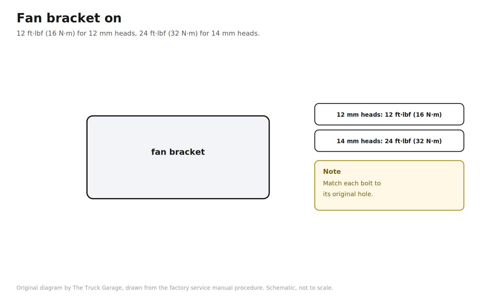
42. Install the fan bracket. Two bolts and two nuts. Torque to 12 ft·lbf (16 N·m) for the 12 mm head bolts, or 24 ft·lbf (32 N·m) for the 14 mm head bolts. Match each bolt to its original hole. [manual]
Original diagram by The Truck Garage. Reinstalling the fan bracket with the two torque values. Schematic, not to scale.
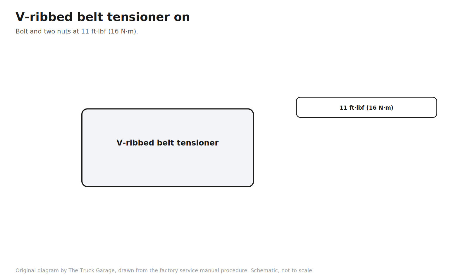
43. Install the V-ribbed belt tensioner. Bolt and two nuts, torqued to 11 ft·lbf (16 N·m). [manual]
Original diagram by The Truck Garage. Reinstalling the V-ribbed belt tensioner. Schematic, not to scale.
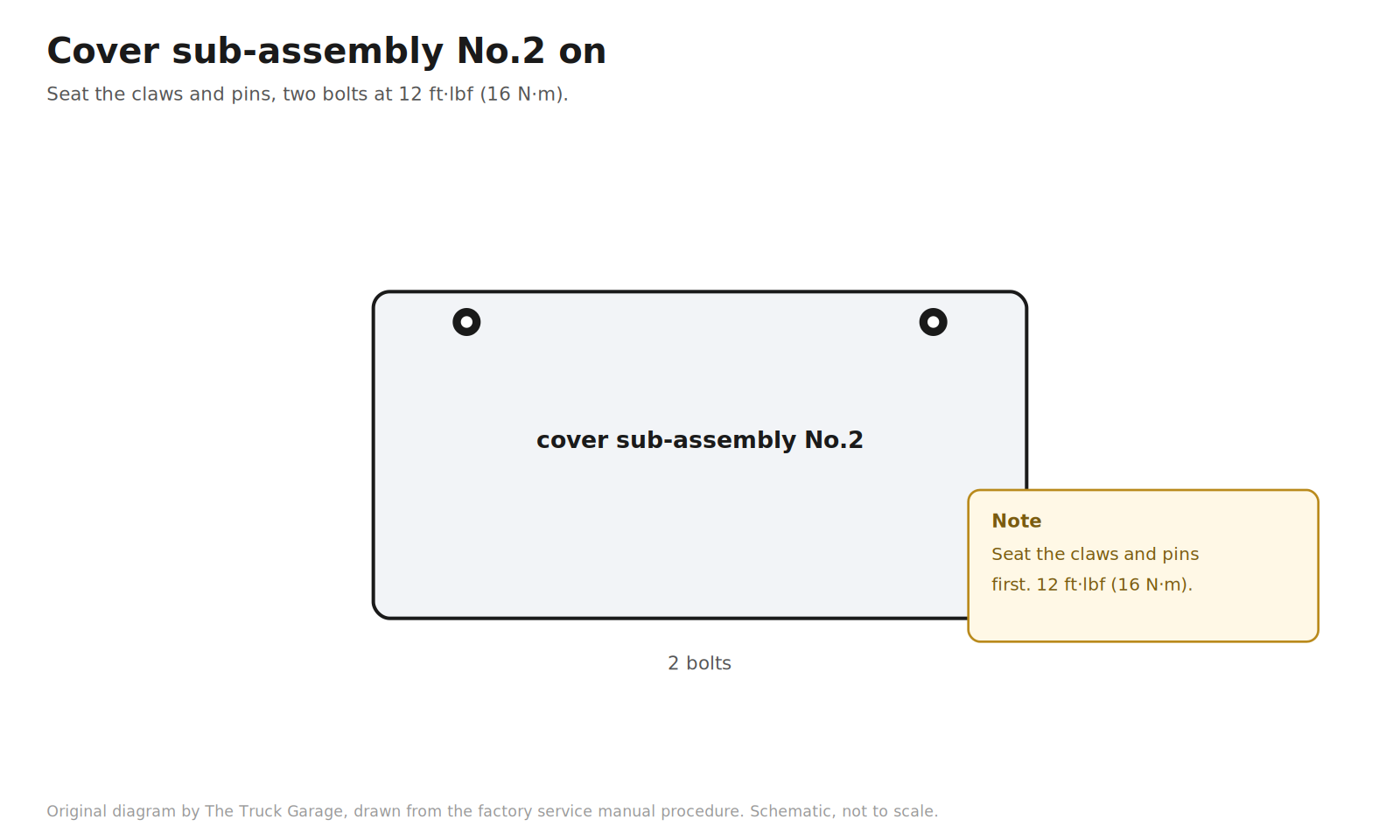
44. Install the timing belt cover sub-assembly No.2. Fit the cover so the claws and pins seat into their mating parts, then install the two bolts and torque to 12 ft·lbf (16 N·m). [manual]
Original diagram by The Truck Garage. Reinstalling cover sub-assembly No.2. Schematic, not to scale.
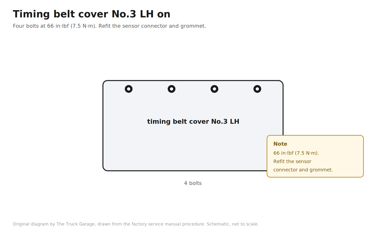
45. Install the timing belt cover No.3 LH. Four bolts, torqued to 66 in·lbf (7.5 N·m). Refit the camshaft position sensor connector and the grommet to the cover. [manual]
Original diagram by The Truck Garage. Reinstalling timing belt cover No.3 LH. Schematic, not to scale.
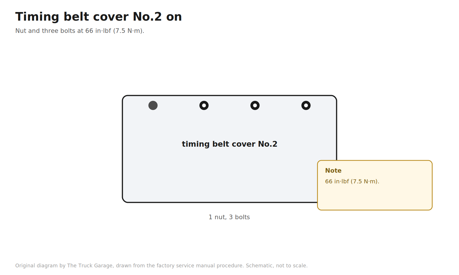
46. Install the timing belt cover No.2. Nut and three bolts, torqued to 66 in·lbf (7.5 N·m). [manual]
Original diagram by The Truck Garage. Reinstalling timing belt cover No.2. Schematic, not to scale.
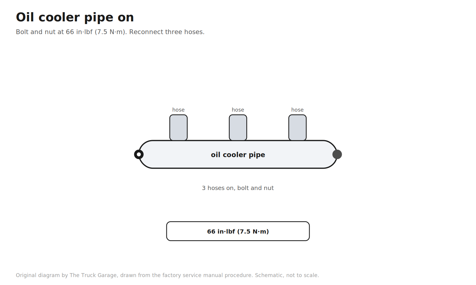
47. Install the oil cooler pipe. Bolt and nut, torqued to 66 in·lbf (7.5 N·m). Reconnect the three hoses. [manual]
Original diagram by The Truck Garage. Reinstalling the oil cooler pipe. Schematic, not to scale.
48. Install the accessory idler pulley No.2. Pulley and cover plate with the bolt, torqued to 29 ft·lbf (39 N·m). [manual]
Original diagram by The Truck Garage. Reinstalling accessory idler pulley No.2. Schematic, not to scale.
49. Install the A/C compressor. Stay, three bolts, and nut. Torque the bolts to 34 ft·lbf (47 N·m) and the nut to 18 ft·lbf (25 N·m). Reconnect the compressor connector. [manual]
Original diagram by The Truck Garage. Reinstalling the A/C compressor with the correct torques. Schematic, not to scale.
50. Install the generator. [manual]
Original diagram by The Truck Garage. Reinstalling the generator (alternator). Schematic, not to scale.
51. Install the power steering vane pump. Nut and two bolts, torqued to 32 ft·lbf (43 N·m). Reconnect the vacuum hose. [manual]
Original diagram by The Truck Garage. Reinstalling the power steering vane pump. Schematic, not to scale.
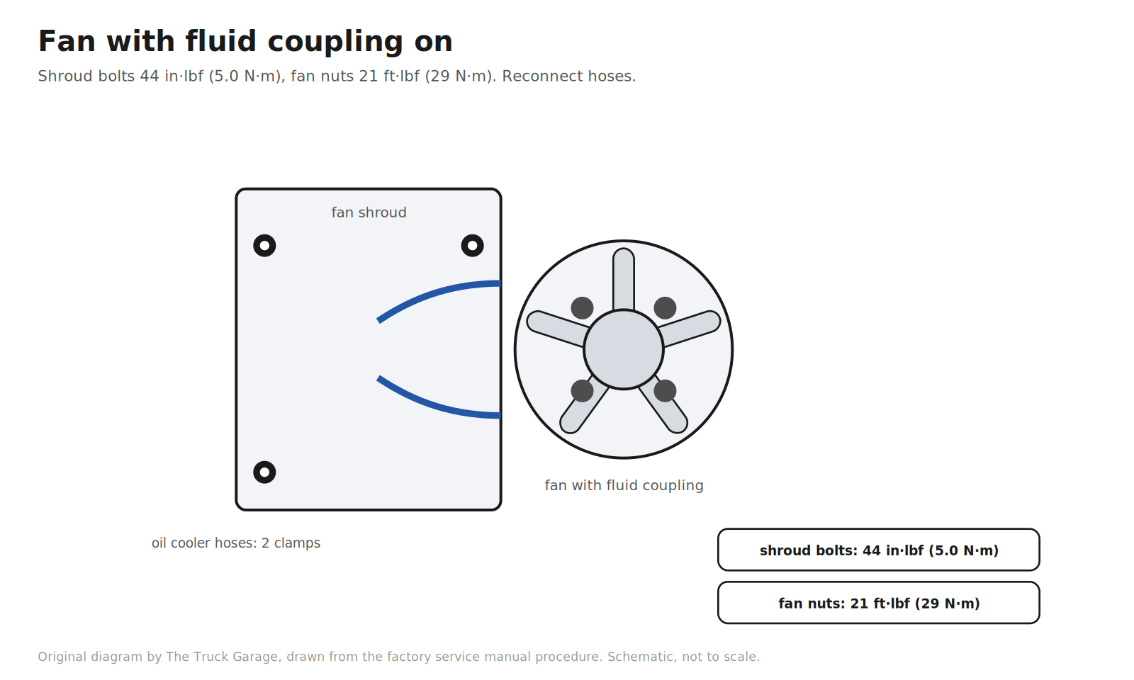
52. Install the fan with fluid coupling. Install the fan pulley. Lower the fan and shroud into the engine room together. Install the shroud with its three bolts, torqued to 44 in·lbf (5.0 N·m). Install the fan with its four nuts, torqued to 21 ft·lbf (29 N·m). Reconnect the two oil cooler hoses and their clamps. [manual]
Original diagram by The Truck Garage. Reinstalling the fan with fluid coupling and the shroud. Schematic, not to scale.
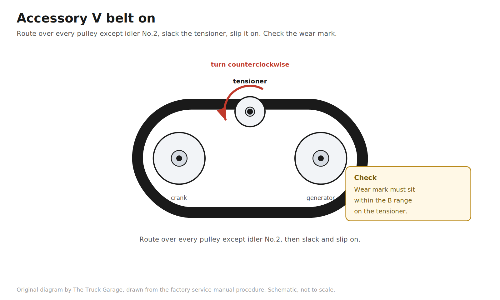
53. Install the accessory V belt. Route the belt over every pulley except idler No.2. Turn the belt tensioner counterclockwise to slack it, then slip the belt onto idler No.2. After installing a new belt, check that the tensioner’s wear mark sits within the B range shown on the tensioner. [manual]
Original diagram by The Truck Garage. Routing the new accessory V belt and checking the tensioner wear mark. Schematic, not to scale.
54. Reinstall the radiator support seal upper, the air cleaner hose, and the engine room covers. [manual]
Original diagram by The Truck Garage. Reinstalling the support seal, air cleaner hose, and covers. Schematic, not to scale.
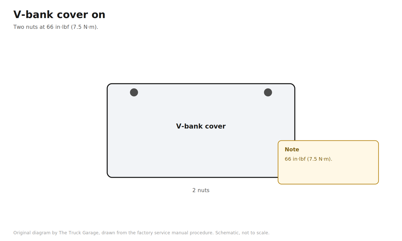
55. Install the V-bank cover. Two nuts, torqued to 66 in·lbf (7.5 N·m). [manual]
Original diagram by The Truck Garage. Reinstalling the V-bank cover. Schematic, not to scale.
Verification and refill
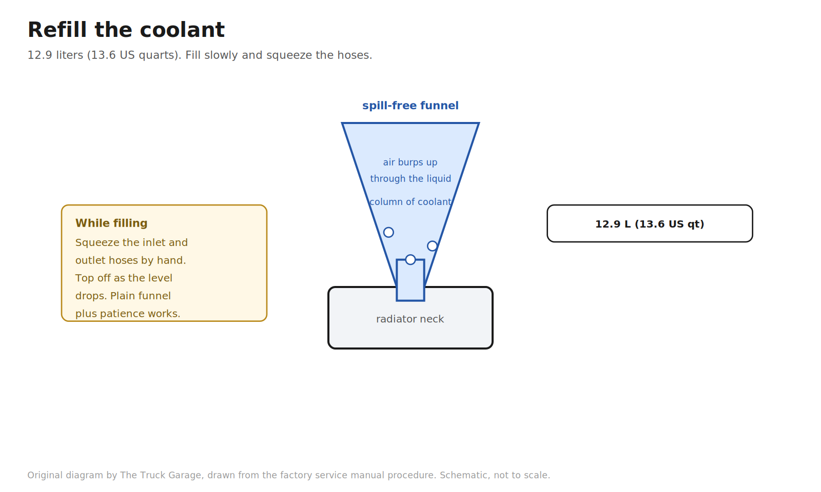
56. Refill the coolant. Slowly fill the cooling system. Capacity is 12.9 liters (13.6 US quarts). Use Toyota Super Long Life coolant or an equivalent high quality ethylene glycol coolant. Do not use plain water alone. Squeeze the inlet and outlet radiator hoses several times by hand while filling. If the coolant level drops, add more. This works air out of the system. Then install the radiator cap. [manual] Shadetree: a spill-free funnel sealed to the radiator neck holds a column of coolant above the system so trapped air burps out through liquid instead of spilling. A plain funnel and the hose-squeezing method above also work. [community]
Original diagram by The Truck Garage. Refilling the coolant with a funnel and squeezing the hoses. Schematic, not to scale.
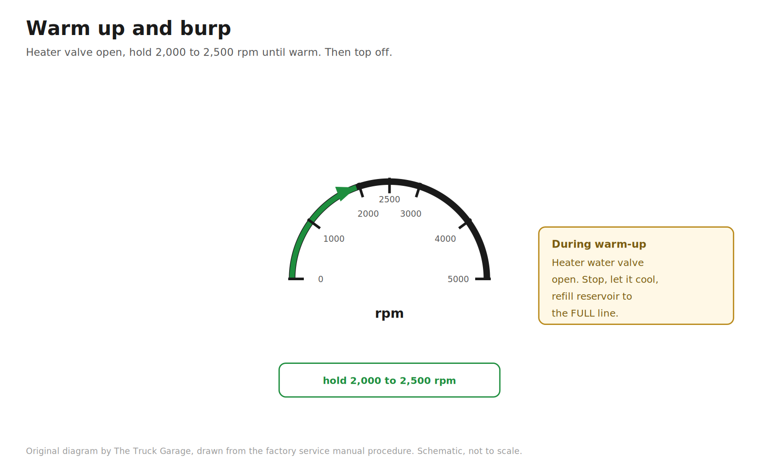
57. Warm up and burp. Start the engine and open the heater water valve. Hold the engine at 2,000 to 2,500 rpm until it warms up. Stop the engine and let the coolant cool down. Then refill the reservoir to the FULL line. [manual]
Original diagram by The Truck Garage. Warming up the engine at 2,000 to 2,500 rpm to burp air. Schematic, not to scale.
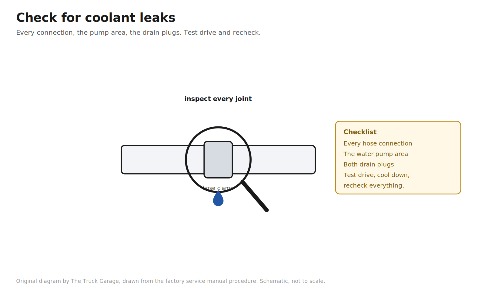
58. Check for coolant leaks. Inspect every hose connection, the water pump area, and the drain plugs. Take a short test drive, let it cool, and check the reservoir level and all connections once more. An air pocket left in the system can cause a sudden overheat, so do not skip the recheck. [community]
Original diagram by The Truck Garage. Checking every connection for coolant leaks. Schematic, not to scale.
FAQ
Can I reuse the old timing belt if it looks fine?
The manual covers reusing a belt and says to check its installation marks, but you are replacing it. A new belt comes in the kit. A belt that looks fine at 90k miles is still a 90k-mile belt, and you have already done all the labor to reach it. [manual] [community]
Do I actually need the factory special tools?
Three matter. A crankshaft holding tool or one of the shadetree equivalents for the damper bolt. A puller for the damper, though loaner sets are free at parts stores and many dampers slide off by hand. And something to compress the tensioner, where a bench vise replaces the press. Everything else is standard sockets. [manual] [community]
What if the timing marks do not line up after the two revolutions?
The belt is a tooth off somewhere. Do not run the engine that way. Remove the belt and reinstall it. Recheck with another two clockwise revolutions until every mark aligns. [manual]
What happens if I accidentally turn the crankshaft with the belt off?
On the VVT-i 2UZ-FE, the pistons and valves share the same space at the wrong angles. If the crank or a cam gets turned with the belt off, stop. Reset everything per the procedure: cams to their marks, crank to its mark via the TDC procedure, then install the belt. Do not force anything that resists. [manual]
Why compress and pin the tensioner instead of just bolting it on?
The tensioner needs slack in the belt to seat properly. Compressing the push rod and pinning it holds the tensioner retracted while you bolt it down and route the belt. Pulling the pin afterward lets it extend against the belt with the correct tension. Bolting it on extended fights the belt and gives you the wrong tension. [manual]
Bottom line
That is the whole job, bolt by bolt, in the factory order. The procedure rewards patience and punishes shortcuts: set the crank before the belt comes off, keep every pulley clean, pin the tensioner before it goes on, torque every fastener to the book, and verify the marks with two clockwise revolutions before anything closes up. Do that and the 2UZ-FE gets its next 90,000 miles.
Sources
2005 Lexus GX470 factory repair manual. All torque specs and procedure steps.
Lexus GX470 scheduled maintenance guide, timing belt interval of 90,000 miles or 108 months: https://carmanuals2.com/lexus/gx470-2005-scheduled-maintenance-guide-22229/page-29/
Starter bump method discussion and breaker bar failures: https://forum.ih8mud.com/threads/is-this-right-to-loosen-the-cranshaft-pulley-with-starter-bump.354272/
Parts store loaner tool programs: https://www.slashgear.com/1473130/everything-to-know-about-oreilly-loaner-tool-program/